6 ControlLogix DC (19.2-30V) Diagnostic Output Module
Publication 1756-IN058D-EN-P - October 2000
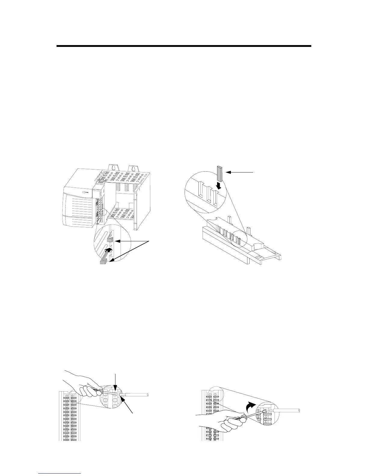
Key the Removable Terminal Block/Interface Module
Wedge-shaped keying tabs and U-shaped keying bands came with
your RTB to prevent connecting the wrong wires to your module.
Key positions on the module that correspond to unkeyed positions
on the RTB. For example, if you key the first position on the module,
leave the first position on the RTB unkeyed.
Reposition the tabs to rekey future module applications.
Wire the Removable Terminal Block
Wire the RTB with a 1/8 inch (3.2mm) maximum flat-bladed
screwdriver before installing it onto the module.
20850–M
1. Insert the U-shaped band as shown.
2. Push the band until it snaps in place.
U-shaped
bands
1. Insert the wedge-shaped tab with rounded edge first.
2. Push the tab until it stops.
20851–M
Wedge-shaped tab
Key the Module Key the RTB/IFM
Spring Clamp RTB Cage Clamp RTB
20860-M 20859-M
1. Strip 7/16 inch (11mm) maximum length of
wire.
2. Insert the screwdriver into the inner hole
of the RTB.
3. Insert the wire into the open
terminal and remove the
screwdriver.
1. Strip 3/8 inch (9.5mm) maximum length of
wire.
2. Insert the wire into the open terminal.
3. Turn the screw clockwise to close the
terminal on the wire.
 Loading...


