ControlLogix DC (19.2-30V) Diagnostic Output Module 7
Publication 1756-IN058D-EN-P - October 2000
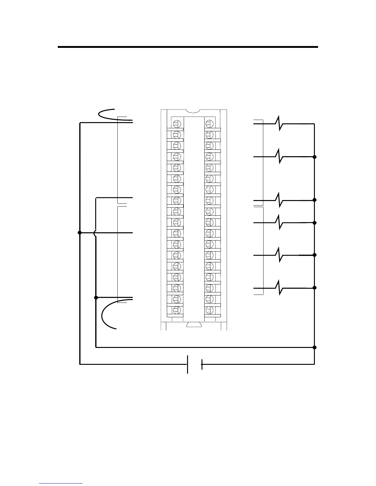
Wire the Module
You can only connect wiring to your module through an RTB or IFM.
The example below shows how to wire the module.
After completing field-side wiring, secure the wires in the strain relief
area with a cable-tie.
12
34
5
6
78
910
1112
1314
1516
1718
1920
2122
2324
2526
2728
2930
31
32
3334
3536
40173-M
+
–
1. All terminals with the same name are connected together on the module. For example,
DC COM can be connected to either terminal marked GND-1.
2. When you daisy chain to other RTBs, always connect the daisy chain to the terminal
directly connected to the supply wire, as shown in the example above.
3. This wiring example shows a single voltage source.
4. If separate power sources are used, do not exceed the specified isolation voltage.
Daisy chain
to other RTBs
DC COM
Group 0 Group 0
Group 1 Group 1
1756-OB16D
+DC-0
+DC-0
+DC-0
+DC-0
+DC-1
+DC-0
+DC-0
+DC-0
GND-0
Not used
+DC-1
+DC-1
+DC-1
+DC-1
+DC-1
+DC-1
GND-1
GND-1
OUT-0
OUT-1
OUT-2
OUT-3
OUT-8
OUT-4
OUT-5
OUT-6
OUT-7
Not used
OUT-9
OUT-10
OUT-11
OUT-12
OUT-13
OUT-14
OUT-15
Not used
Daisy chain to other RTBs
Allen-Bradley Drives
 Loading...


