ControlLogix Voltage/Current Output Module 11
Publication
1756-IN016B-EN-P - November 2003
If you cannot ground at the field device, follow these steps:
1. Prepare one end of the cable as shown in step 1.
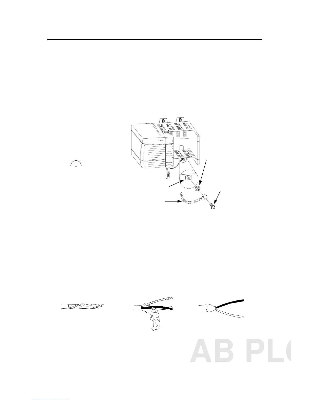
2. Ground at an earth ground on the chassis as shown below.We
recommend grounding the drain wire at the field-side. If you
cannot ground at the field-side, ground at an earth ground on
the chassis as shown.
Connect the insulated wires to the RTB.
Connect ungrounded end of the cable
1. Prepare the non-grounded end of the cable.
20918-M
Connect the drain wire to a
chassis mounting tab.
Use any chassis mounting tab
that is designated as a functional
earth ground terminal. This
symbol appears near
the tab.
Chassis mounting tab
Drain wire with ground lug
4M or 5M (#10 or #12)
phillips screw and star
washer (or SEM screw)
4M or 5M (#10 or
#12) star washer
A. Remove a length
of cable jacket
from the
connecting cable.
B. Pull the foil shield
and bare drain
wire from the
insulated wire.
C. Cut foil shield and drain wire
back to the cable casing and
apply shrink wrap, exposing
only the insulated wires.
43182
AB PLCs
 Loading...


