1785-UM022B-EN-P - February 2002
ControlNet Diagnostics File Layout F-3
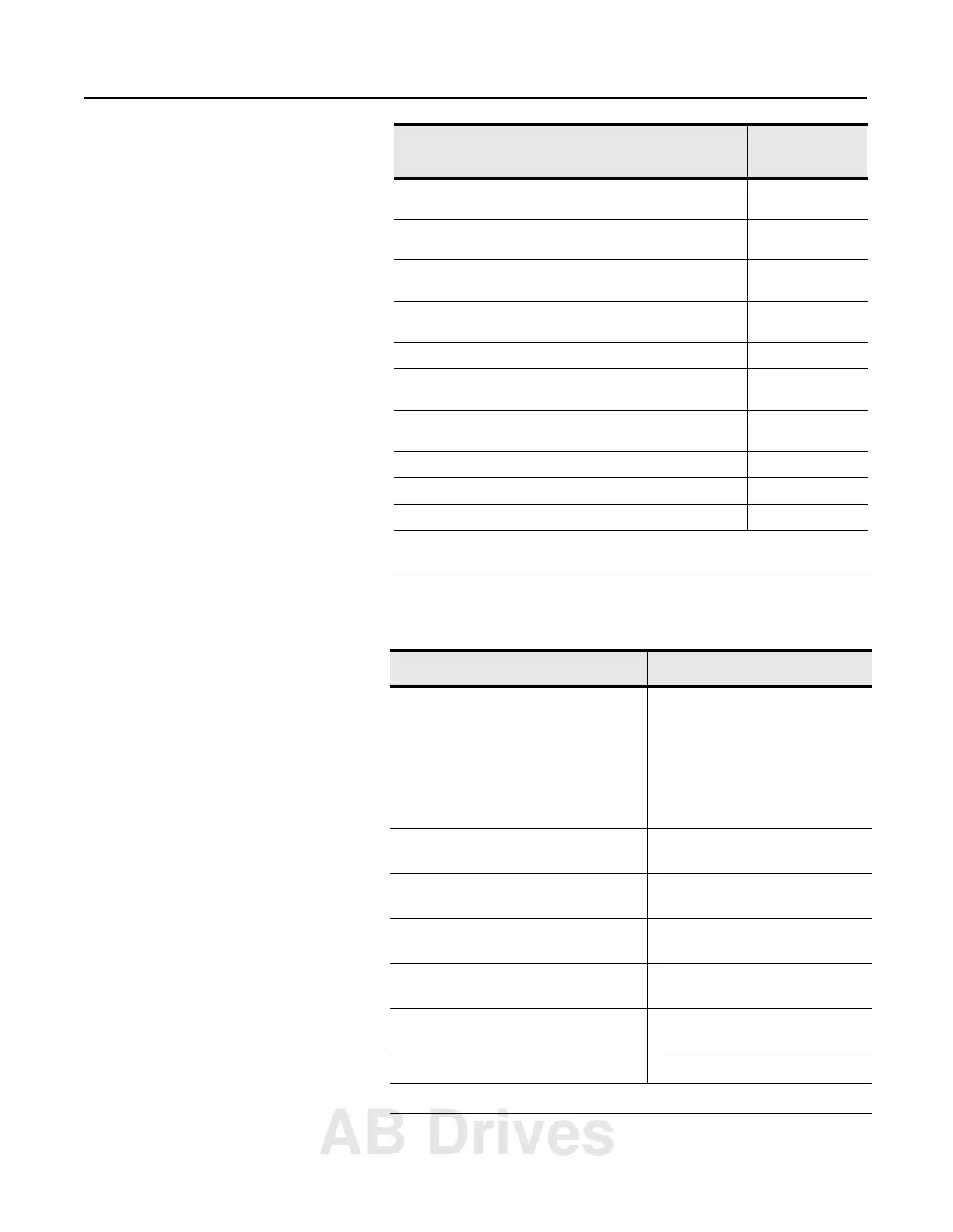
The following table describes each bit in word 23 (Channel status and
Media bits) of the diagnostic file.
Maximum number of simultaneously open target Message
Router connections (always less than or equal to 32)
53
Accumulated number of target Message Router connection
timeouts
54
Current number of used unconnected clients
(always less than or equal to 8)
55
Maximum number of simultaneously used unconnected clients
(always less than or equal to 8)
56
Accumulated number of unconnected client timeouts 57
Current number of used unconnected servers
(always less than or equal to 20)
58
Maximum number of simultaneously used unconnected servers
(always less than or equal to 20)
59
Accumulated number of unconnected server timeouts 60
Accumulated number of dropped unconnected requests 61
Accumulated number of JITT overruns 62
1
The file offset in the user-specified ControlNet diagnostics file. For example, if you
specified N12, then the Buffer Errors would be located in N12:0, bits 15 - 00.
Bit(s): Description: Values:
2 - 0 channel A LED state 000 = off
001 = green
010 = flashing green/off
011 = flashing red/off
100 = flashing red/green
101 = railroading red/off
110 = railroading red/green
111 = red
5 - 3 channel B LED state
6 redundancy warning 0 = normal
1 = non-selected channel is unusable
7 active channel 0 = channel B active
1 = channel A active
8 repeater mode 0 = device set for normal mode
1 = device set for repeater mode
9 channel A media mode 0 = configured for Coaxial
1 = configured for fiber
10 channel B media mode 0 = configured for Coaxial
1 = configured for fiber
15 - 11 reserved
Note: A value of 219 in word 23 indicates that the ControlNet network is not usable.
Field Names
File Offset
1
(word;bits)
AB Drives

 Loading...


