40 Rockwell Automation Publication 842E-UM001C-EN-P - September 2016
Chapter 4 Installation
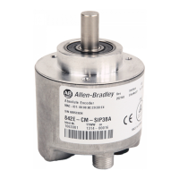
4. Mount the encoder and tighten with three size M4 mounting screws
(not supplied).
5. Center the flexible coupling and tighten the set screws.
6. Rotate the machine slowly and verify that the flexible coupling is not
deforming beyond specifications.
7. Align machine to its mechanical zero or home position.
8. Remove the screw cover on the back of the encoder and press the preset
push button to change the preset value to the current shaft position
value. (The factory preset value is zero.)
9. Replace the screw cover.
Mounting with a Hollow Shaft
1. Loosen the screw on the clamping ring with a 2.5 mm (0.098 in.) star
driver.
2. Slide the encoder onto the mating shaft until the flex mount rests on the
machine surface.
3. Hold encoder firmly and mark the two mounting holes. (If mounting
holes exist, proceed to Step 6.)
4. Slide the encoder off. To accept M4 (or equivalent) screws, drill, and tap
the marked holes.
5. Slide the encoder back onto the shaft until the flex mount rests on the
machine surface.
6. Attach the encoder with two M4 (or equivalent) screws.
7. Tighten the clamping ring screw to 1.1 Nm (10 in–lb).
8. Align machine to its mechanical zero or home position.
9. Remove the screw cover on the back of the encoder and press the preset
push button to change the preset value to the current shaft position
value. (The factory preset value is zero.)
10. Replace the screw cover.
IMPORTANT Be sure that the mating shaft is chamfered and grease-free.
ATTENTION: The encoder slides freely onto the shaft; if not, do not force.
Check the shaft for interferences such as gouges, burrs, rust, or size.
IMPORTANT Do not stress the flex mount while tightening the screws.
 Loading...