42 Rockwell Automation Publication 842E-UM001C-EN-P - September 2016
Chapter 4 Installation
Pin Assignments
Preset Push Button
To preset the position of the encoder, remove the screw cover from the back of
the encoder and briefly press the Preset button inside (see figure on page 41
and “Preset Function” on page 62
).
Network Address Switches
You can use the three Network Address switches to set the IP address of the
encoder (see Figure 3 on page 47
and “Setting the IP address” on page 45).
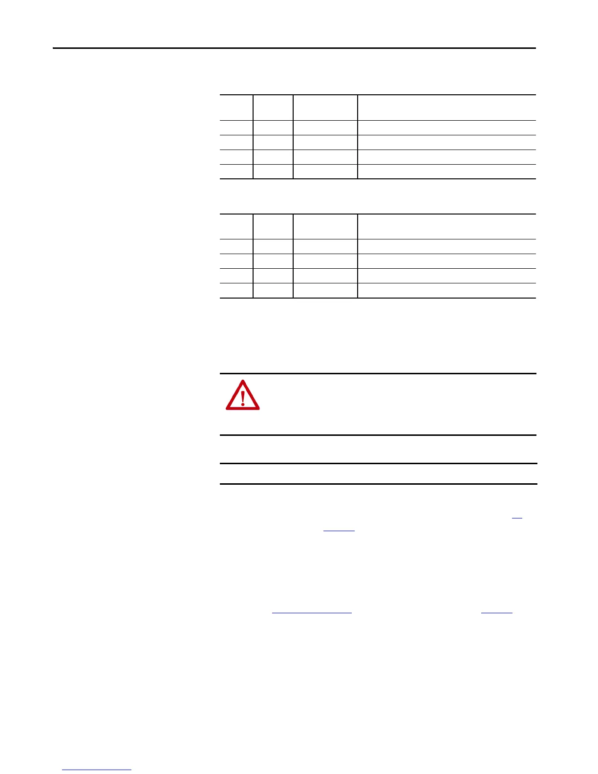
Pin Signal Mating Cable
Wire Color
Function
1 Versus Brown Supply voltage 10…30V DC
2WhiteDo not use
3 GND Blue 0V DC (ground)
4BlackDo not use
Table 1 - Voltage Supply
Pin Signal Mating Cable
Wire Color
Function
1TxD+White orangeEthernet
2 RxD+ White green Ethernet
3 TxD– Orange Ethernet
4RxD–Green Ethernet
Table 2 - Ethernet Link Connections – Link 1 and Link 2
ATTENTION: Pressing the preset push button results in a change of position
reading.
The change in position causes unexpected motion, which could result in
personal injury or damage to the product or equipment.
IMPORTANT Press the preset button briefly, no longer than one second.
 Loading...