Do you have a question about the Allen-Bradley EtherNet/IP 842E-SIP1BA and is the answer not in the manual?
Explains different types of safety warnings like WARNING, ATTENTION, IMPORTANT, SHOCK HAZARD, BURN HAZARD, ARC FLASH HAZARD.
Introduces the manual's content, including audience, purpose, and conventions.
Identifies the target audience responsible for installing, programming, or troubleshooting the encoder.
Outlines the manual's goal to serve as a reference for installing, wiring, and troubleshooting the encoder.
Lists other Rockwell Automation publications for additional information on related products and systems.
Explains conventions used in the manual, such as bullet points, numbered lists, and italic type.
Specifies that only authorized and trained personnel should install, commission, and service the encoder.
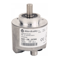
States that the encoder is an instrument manufactured according to industrial regulations and must be operated within an EtherNet/IP network.
Provides essential safety procedures for installation, operation, and maintenance, emphasizing qualified personnel.
Details the disposal methods for various encoder components like packaging, shaft, flange, housing, and electronic assemblies.
Explains that encoders measure shaft rotation for speed, distance, RPM, and position.
Describes incremental encoders as cost-effective solutions for monitoring shaft position or speed in various applications.
Explains absolute encoders provide a unique digital output for each shaft position, ensuring true position availability after power interruptions.
Lists key features of the 842E EtherNet/IP encoder, including CIP profile support, topology compatibility, and resolution.
Details parameters like count direction, counts per revolution, preset value, and IP addressing configurable via EtherNet/IP.
Explains the EDS file contains measurement and operating mode information, integrated using network configuration tools.
Describes how the encoder acquires rotary position using an internal coded disk and outputs a digital numeric value.
Differentiates single-turn encoders for one revolution position and multi-turn for multiple revolution positions.
Explains how steps per revolution and total resolution can be scaled and adapted for specific applications.
Summarizes unique features like design, robustness, precision, mounting options, and upgrade compatibility.
Explains CIP as the application layer protocol implemented by EtherNet/IP for encoder communication.
Details how EtherNet/IP uses TCP/IP and UDP/IP for communication, differentiating implicit and explicit messaging.
Defines MAC addresses as unique identifiers for devices on the network, consisting of manufacturer and device-specific bytes.
Describes the standard Ethernet frame structure containing header, data field, and trailer, including MAC IDs.
Explains the Producer/Consumer model replacing master/slave, reducing traffic, and enabling efficient data exchange.
Defines RPI as the update rate for data exchange between devices, specifying how often data is produced or sent.
Introduces the three network topologies supported: Star, Linear, and Device Level Ring (DLR).
Describes the star topology where devices connect to a central switch, noting Link 1 usage and Link 2 inactivity.
Explains linear topology using daisy-chaining, simplifying installation but disconnecting devices downstream from a break.
Details DLR as a fault-tolerant ring network that tolerates breaks by sending signals in both directions.
Explains the endless shaft feature for multi-turn encoders, removing resolution restrictions and allowing flexible scaling.
Provides specific attribute settings (ID 0Eh, 11h, 7Dh, 7Eh, 7Fh) required to enable the endless shaft functionality.
Lists key features including scaling function control, endless shaft functionality, nominator, divisor, and total measuring range.
Defines core CIP object model terms: Class, Instance, Attribute, and Service, used for network communication.
Describes the Position Sensor Object (Class 23h) for administering device-specific data like position and counting direction.
Details the Identity Object (Class 01h) containing node information, including vendor ID, product code, and revision.
Explains the Assembly Object (Class 04h) for assembling attributes from other objects into a single object for I/O messages.
Illustrates how I/O data is retrieved/output via instances, detailing data format for various attributes.
Covers mechanical aspects of installation, including shaft rotation direction and mounting procedures.
Illustrates and explains clockwise (CW) and counterclockwise (CCW) shaft rotation as viewed from the shaft side.
Provides step-by-step instructions for mounting the encoder with a solid shaft using a flexible coupling.
Offers detailed steps for mounting the encoder onto a hollow shaft, including chamfered shaft preparation and screw attachment.
Covers electrical connections, wiring instructions, and the function of network address switches.
Explains the electrical connections on the housing and the purpose of the 4-pin M12 connector for power and Ethernet.
Details pin assignments for voltage supply and Ethernet link connections, including wire colors and functions.
Describes the function and usage of the preset push button for setting the encoder's position value.
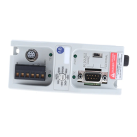
Explains how to use the three network address switches to set the encoder's IP address.
Lists technical electrical specifications including operating voltage, power consumption, load current, resolution, and accuracy.
Outlines methods for assigning an IP address to the encoder, using network switches or BOOTP/DHCP.
Provides steps to set the last octet of the IP address using network switches for a 192.168.1.xxx scheme.
Details how to use BOOTP/DHCP server and network switches to automatically assign an IP address upon power-up.
Shows a sample system setup including a CompactLogix processor, Ethernet switch, and the 842E encoder.
Explains the need for encoder configuration and the use of RSLogix 5000 software (version 18 or later).
Introduces RSLogix 5000 software and its role in setting encoder configuration, with instructions for version 20.
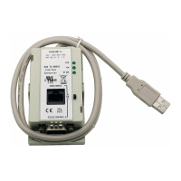
Describes how to use RSLinx Classic to verify the encoder's IP address and its integration into the control system.
Guides the user to install the encoder's Add-on Profile, referencing Appendix A for detailed steps.
Explains how to configure the encoder's name, description, and IP address within the RSLogix 5000 module properties.
Details setting the IP address for the encoder, either on a private network or via manual configuration.
Covers changing module definition settings like series, revision, electronic keying, connection, and input data.
Explains settings on the Connection tab, including Requested Packet Interval (RPI) and fault handling options.
Describes the Module Info tab for viewing read-only identification and status data of the encoder module.
Details configuring encoder scaling, direction, and velocity units through the Configuration tab.
Explains how to configure IP settings manually or automatically, including IP address, subnet mask, and DNS servers.
Describes the Network tab for viewing network topology and status, and refreshing communication with the encoder.
Lists the default parameters the encoder is supplied with, such as direction, scaling, and resolution.
Explains how to set the encoder's position value to zero using the preset function via button or EtherNet/IP.
Describes how encoder tags are loaded into controller tags and how to access them.
Details the configuration image table tags, including Counterclockwise direction and Velocity Units status.
Explains the input image table tags, showing Fault, Position, Alarm, and Warning status.
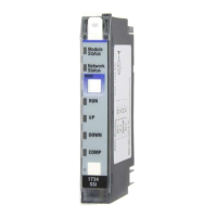
Explains the meaning of the Mod, Net, and Encoder status indicators on the encoder's back panel.
Describes the states of the Net status indicator (OFF, Green blinking, Green, Red blinking, Red) related to power and connection.
Details the states of the Mod status indicator (OFF, Green, Green blinking, Red blinking, Red) related to device operational status.
Explains the states of the Encoder status indicator (OFF, Green blinking, Green, Red blinking, Red) indicating errors or operational status.
Describes the Link 1/2 status indicators showing physical connection status like no link, connection established, or data transmission.
Explains the encoder's self-test triggered by attribute 13, detecting errors through the fault header.
Introduces how to retrieve warnings, alarms, and errors using implicit and explicit messages via the position sensor object.
Lists supported warnings (Attribute 47+48) related to velocity, acceleration, position limits, and voltage.
Explains how alarms are coded in attributes 44+45 and affect the alarm flag (Attribute 47) and Net status indicator.
Details supported alarms (Attribute 44+45) and the sensor error table for specific error conditions.
Provides a table listing sensor errors such as over temperature, voltage detection, and position errors with their descriptions.
Lists common error messages from RSLogix 5000 software, including connection request errors and timeouts, with possible causes.
Introduces the Add-on Profile (AOP) for RSLogix 5000, explaining its purpose in simplifying device configuration.
Guides users through the steps to install the Add-on Profile, including locating and executing the setup executable.
Demonstrates how to use RSLogix 5000 for linear scaling, calculating steps per revolution and total resolution for a linear cart.
Details the process of creating a project file in RSLogix 5000 and configuring the controller IP address.
Guides on sending an explicit message to set the encoder's preset value and confirms message reception.
Explains how to create a message to read the encoder's preset value and initialize the message instruction.
Demonstrates obtaining the encoder's runtime in seconds by creating a message to read the runtime value.
| Model | 842E-SIP1BA |
|---|---|
| Category | Media Converter |
| Series | 842E |
| Protocol | EtherNet/IP |
| Manufacturer | Allen-Bradley |
| Fiber Ports | 1 |
| Input Voltage | 24V DC |
| Operating Temperature | -40°C to 75°C |
| Storage Temperature | -40°C to 85°C |
| Humidity | 5% to 95% non-condensing |