Kinetix 7000 High Power Servo Drives 11
Rockwell Automation Publication 2099-IN003C-EN-P - June 2015
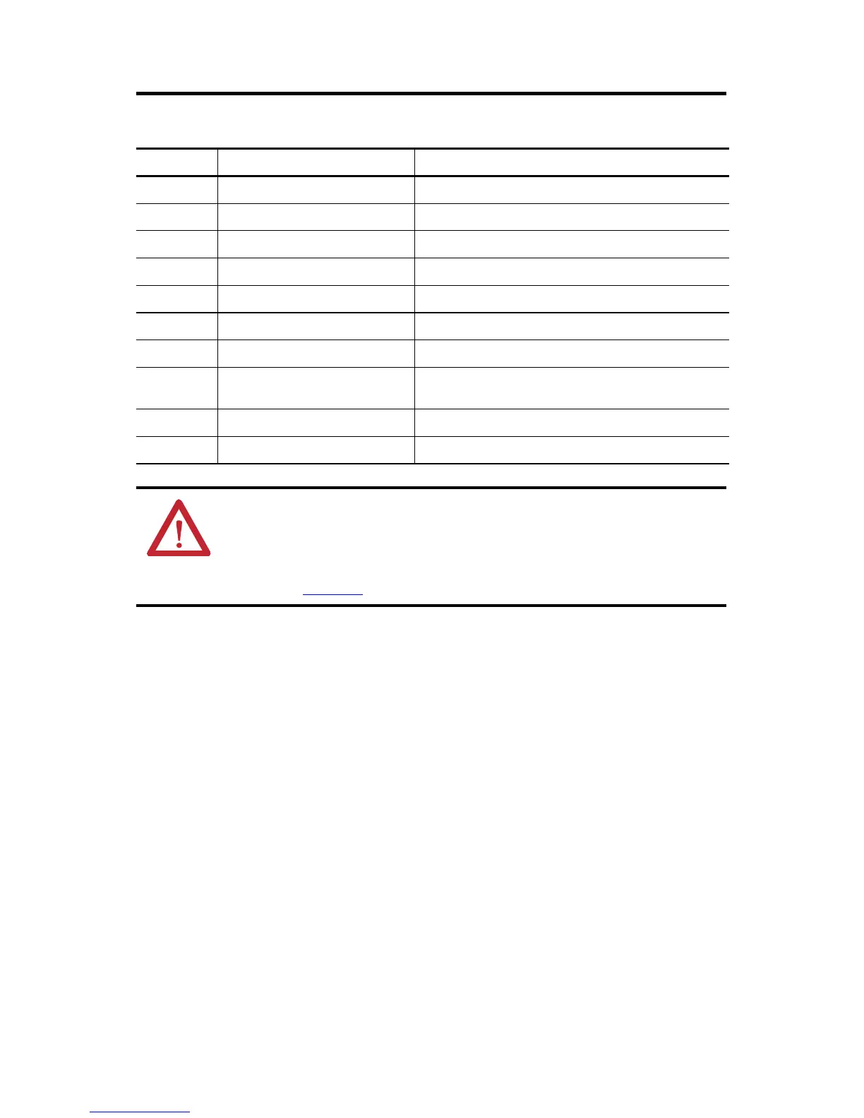
Kinetix 7000 Drive Connectors
Designator Description Connector
SO Safe-off 9-position plug/header
IOD User I/O (drive) 26-pin high-density D-shell
MF Motor feedback 15-pin high-density D-shell (female)
AF Auxiliary feedback 15-pin high-density D-shell (male)
CP Control input power (drive) 2-position terminal
GPIO General purpose I/O 8-position plug/header
GPR General purpose relay 6-position plug/header
PTB Power terminal block
Screw terminals for main power, DC bus, motor power (MP), and fan
power (if required)
DPI Drive peripheral interface 6-position circular connector (factory use only)
Tx and Rx SERCOS transmit and receive SERCOS fiber-optic (2)
ATTENTION: To avoid damage to the SERCOS Rx and Tx connectors, use only finger-tight torque
when attaching the fiber-optic cables to a Kinetix 7000 drive. Do not use a wrench or any other
mechanical assistance.
For more information, refer to Fiber-optic Cable Installation and Handling Instructions,
publication 2090-IN010
.
 Loading...


