10 Kinetix 7000 High Power Servo Drives
Rockwell Automation Publication 2099-IN003C-EN-P - June 2015
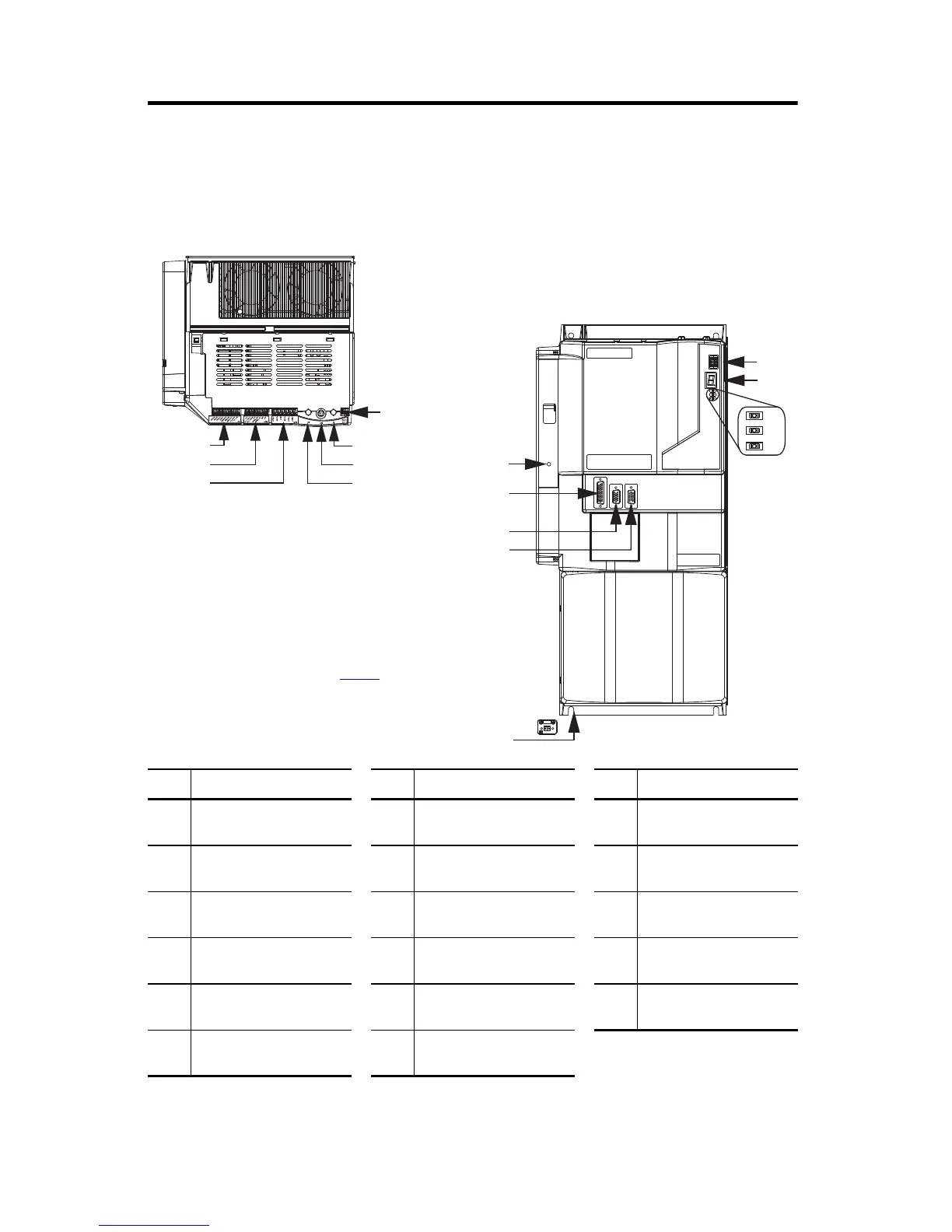
Connector Data
The location of connectors and indicators is identical, regardless of the physical size of the drive.
Kinetix 7000 Drive Features and Indicators
Item Description Item Description Item Description
1
General purpose (GPR)
connector
7
SERCOS receive (Rx)
connector
13
SERCOS node address
switches
2
General purpose (GPIO)
connector
8
Control power (CP) connector
(facing down)
14
Seven-segment fault status
indicator
3 Safe-off (SO) connector 9
Auxiliary feedback (AF)
connector
15 Drive status indicator
4
SERCOS communication rate
and optical power switches
10
Motor feedback (MF)
connector
16 COMM status indicator
5
SERCOS transmit (Tx)
connector
11 I/O (IOD) connector 17 Bus status indicator
6 DPI connector 12
Control power status
indicator
15
16
17
13
14
4
3
2
1
5
6
7
12
8
11
10
9
Kinetix 7000 Drive Module
(2099-BM07-S drive, top view is shown)
Kinetix 7000 Drive Module
(2099-BM07-S drive, front view is shown)
Power Terminal Block (beneath cover)
Refer to page
16 for terminal block configurations.
 Loading...


