6 Kinetix 7000 High Power Servo Drives
Rockwell Automation Publication 2099-IN003C-EN-P - June 2015
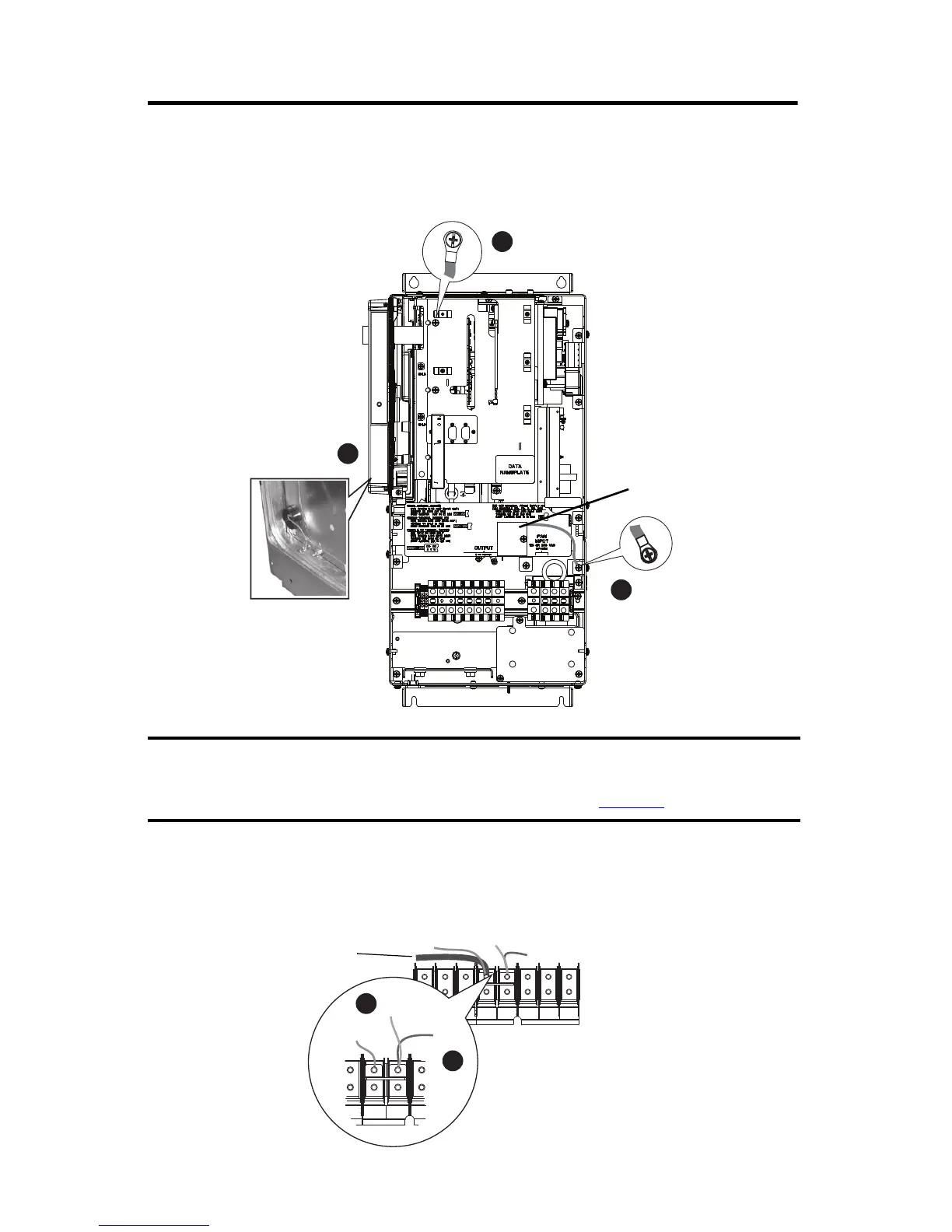
Remove the Ground Wires on 2099-BM09-S and 2099-BM10-S Drives
The common-mode capacitor ground wire is indicated by callout 3 and the MOV/input filter
cap ground wire is indicated by callout 4.
Remove the Ground Wires on 2099-BM11-S and 2099-BM12-S Drives
The common-mode capacitor ground wire is indicated by callout 5 and the MOV ground wire is
indicated by callout 6.
You must remove the DC-DC converter and drive top cover to access and remove the
common-mode capacitor ground wire. Refer to the Kinetix 7000 DC-DCConverter and
ControlBoard Kits Installation instructions, publication 2099-IN002
.
CM Cap - Older Drives
CM Cap - Newer Drives
MOV
MOV/Input
Filter Cap
4
U
T1
V
T2
W
T3
R
L1
S
L2
INPUTOUTPUT
T
L3
PE PE
PE PE
MOV
CM Cap
 Loading...


