2 Rockwell Automation Publication 1763-UM002E-EN-P - October 2015
Chapter 1 MicroLogix 1100 Embedded Web Server
Connect the
MicroLogix 1100 controller
to the Network
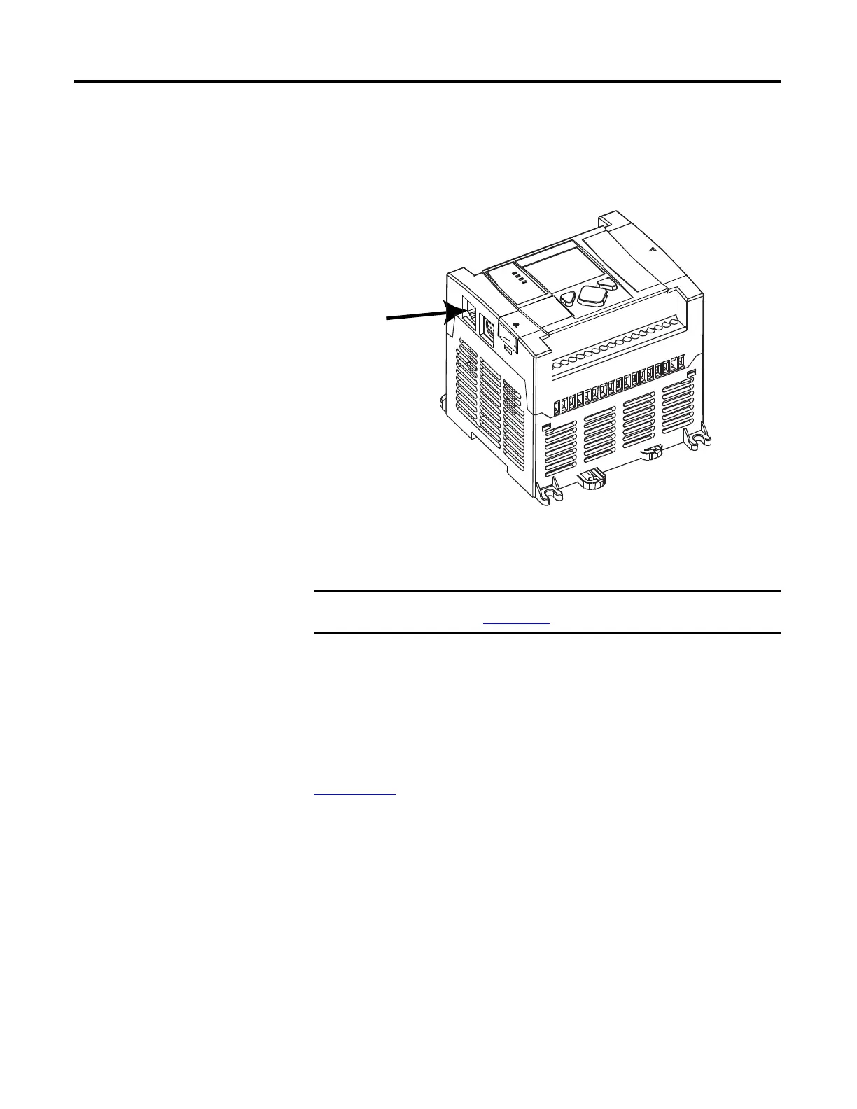
1. Connect the module to the network
Connect the MicroLogix 1100 controller to the Ethernet network. The RJ-45
connector is on the left-hand side of the module.
2. Obtain an IP address.
By default, the MicroLogix 1100 controller is BOOTP enabled. If you connect
the MicroLogix 1100 controller to a network that has a BOOTP server, that
server will assign an IP address to the MicroLogix 1100 controller and the LCD
screen of the MicroLogix 1100 controller will display BOOTP IP address.
If your network does not have a BOOTP server, use one of the methods
described in the MicroLogix 1100 Programmable Controllers User Manual
1763-UM001
to assign an IP address to the MicroLogix 1100 controller.
For more information, see MicroLogix1100 Programmable Controllers
User Manual, 1763-UM001
.

 Loading...


