Publication 1762-RM001C-EN-P
6-8 Using High-Speed Outputs
PTO Output (OUT)
The PTO OUT (Output) variable defines the output (O0:0/2 or O0:0/3)
that the PTO instruction controls. This variable is set within the function
file folder when the control program is written and cannot be set by the
user program.
•
When OUT = 2, PTO pulses output 2 (O0:0.0/2) of the embedded
outputs (1762-L24BXB, 1762-L40BXB, and 1764-28BXB).
•
When OUT = 3, PTO pulses output 3 (O0:0.0/3) of the embedded
outputs (1764-28BXB only).
PTO Done (DN)
The PTO DN (Done) bit is controlled by the PTO sub-system. It can be
used by an input instruction on any rung within the control program. The
DN bit operates as follows:
•
Set (1) - Whenever a PTO instruction has completed its operation
successfully.
•
Cleared (0) - When the rung the PTO is on is false. If the rung is false
when the PTO instruction completes, the Done bit is set until the next
scan of the PTO instruction.
PTO Decelerating Status (DS)
The PTO DS (Decel) bit is controlled by the PTO sub-system. It can be
used by an input instruction on any rung within the control program. The
DS bit operates as follows:
•
Set (1) - Whenever a PTO instruction is within the deceleration phase
of the output profile.
•
Cleared (0) - Whenever a PTO instruction is not within the
deceleration phase of the output profile.
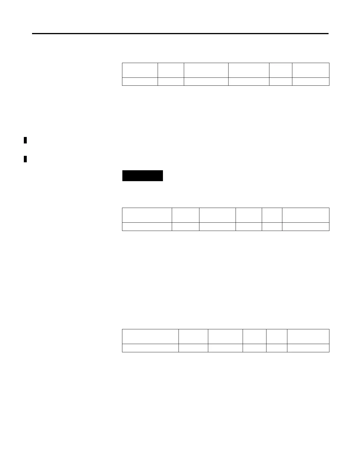
Sub-Element
Description
Address Data Format Range Type User Program
Access
OUT - Output PTO:0.OUT word (INT) 2 or 3 control read only
NOTE
Forcing an output controlled by the PTO while it is
running stops all output pulses and causes a PTO error.
Sub-Element
Description
Address Data Format Range Type User Program
Access
DN - Done PTO:0/DN bit 0 or 1 status read only
Sub-Element
Description
Address Data Format Range Type User Program
Access
DS - Decelerating Status PTO:0/DS bit 0 or 1 status read only

 Loading...


