Publication 1762-RM001C-EN-P
Relay-Type (Bit) Instructions 7-7
Use the OSR and OSF instructions to trigger an event to occur one time.
These instructions trigger an event based on a change of rung state, as
follows:
•
Use the OSR instruction when an event must start based on the
false-to-true (rising edge) change of state of the rung.
•
Use the OSF instruction when an event must start based on the
true-to-false (falling edge) change of state of the rung.
These instructions use two parameters, Storage Bit and Output Bit.
•
Storage Bit - This is the bit address that remembers the rung state from
the previous scan.
•
Output Bit - This is the bit address which is set based on a
false-to-true (OSR) or true-to-false (OSF) rung transition. The Output
Bit is set for one program scan.
To re-activate the OSR, the rung must become false. To re-activate the
OSF, the rung must become true.
Addressing Modes and File Types can be used as shown in the following
table:
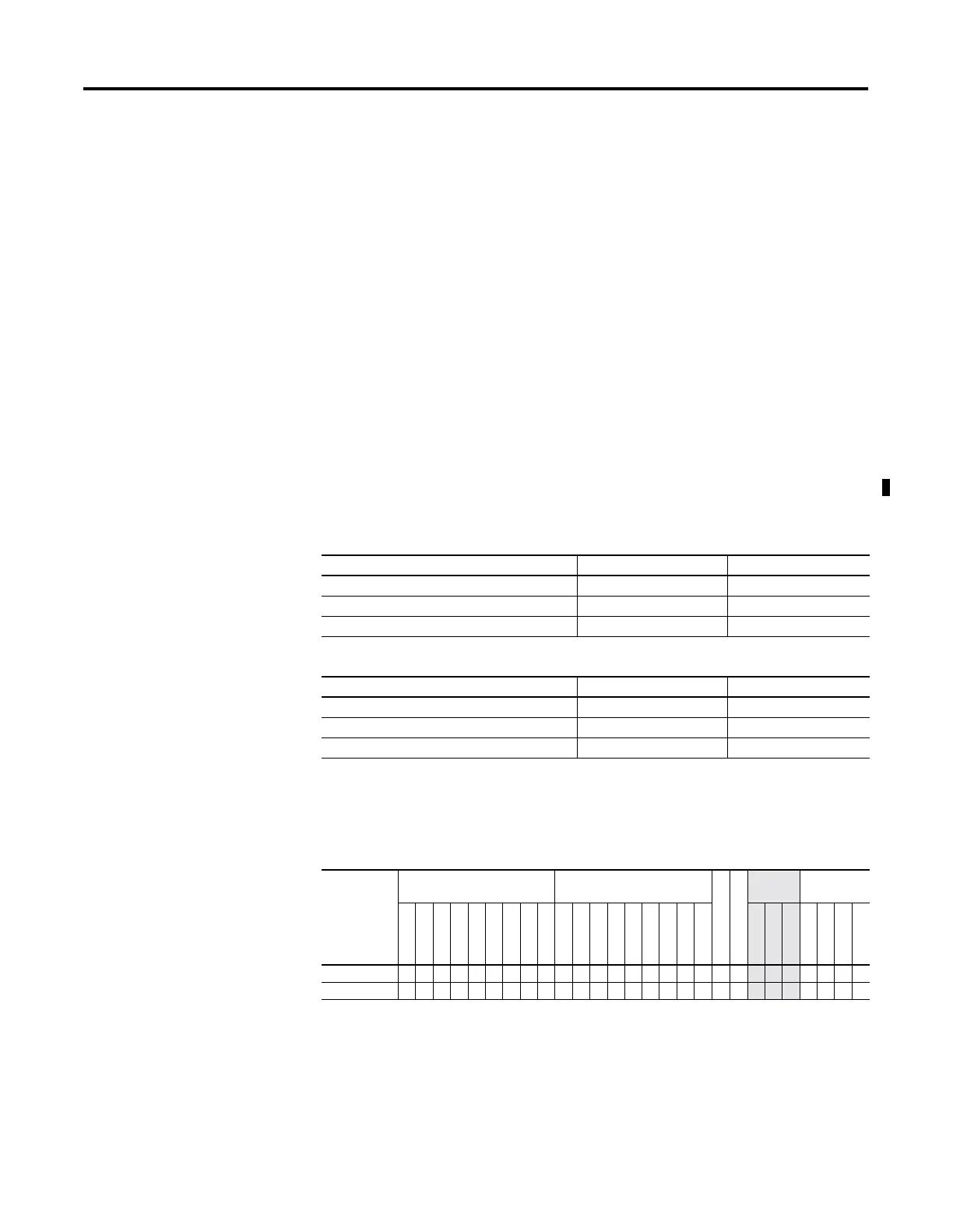
Table 7.12 OSR Storage and Output Bit Operation
Rung State Transition Storage Bit Output Bit
false-to-true (one scan) bit is set bit is set
true-to-true bit is set bit is reset
true-to-false and false-to-false bit is reset bit is reset
Table 7.13 OSF Storage and Output Bits Operation
Rung State Transition Storage Bit Output Bit
true-to-false (one scan) bit is reset bit is set
false-to-false bit is reset bit is reset
false-to-true and true-to-true bit is set bit is reset
Table 7.14 OSR and OSF Instructions Valid Addressing Modes and File Types
For definitions of the terms used in this table see Using the Instruction Descriptions on page4-2.
Parameter
Data Files Function Files
CS - Comms
IOS - I/O
Address
Mode
Address
Level
O
I
S
B
T, C, R
N
ST
L
MG, PD
RTC
HSC
PTO, PWM
STI
EII
BHI
MMI
DAT
TPI
Immediate
Direct
Indirect
Bit
Word
Long Word
Element
Storage Bit •• • •
Output Bit •• ••• •
• •

 Loading...


