Publication 1762-RM001C-EN-P
File Instructions 14-5
If you wish to shift more than one bit per scan, you must create a loop in
your application using the JMP, LBL, and CTU instructions.
This instruction uses the following operands:
•
File - The file operand is the address of the bit array that is to be
manipulated.
•
Control - The control operand is the address of the BSL’s control
element. The control element consists of 3 words:
•
Bit Address - The source is the address of the bit to be transferred into
the bit array at the first (lowest) bit position.
•
Length - The length operand contains the length of the bit array in
bits. The valid data range for length is from 0 to 2048.
Addressing Modes and File Types can be used as shown in the following
table:
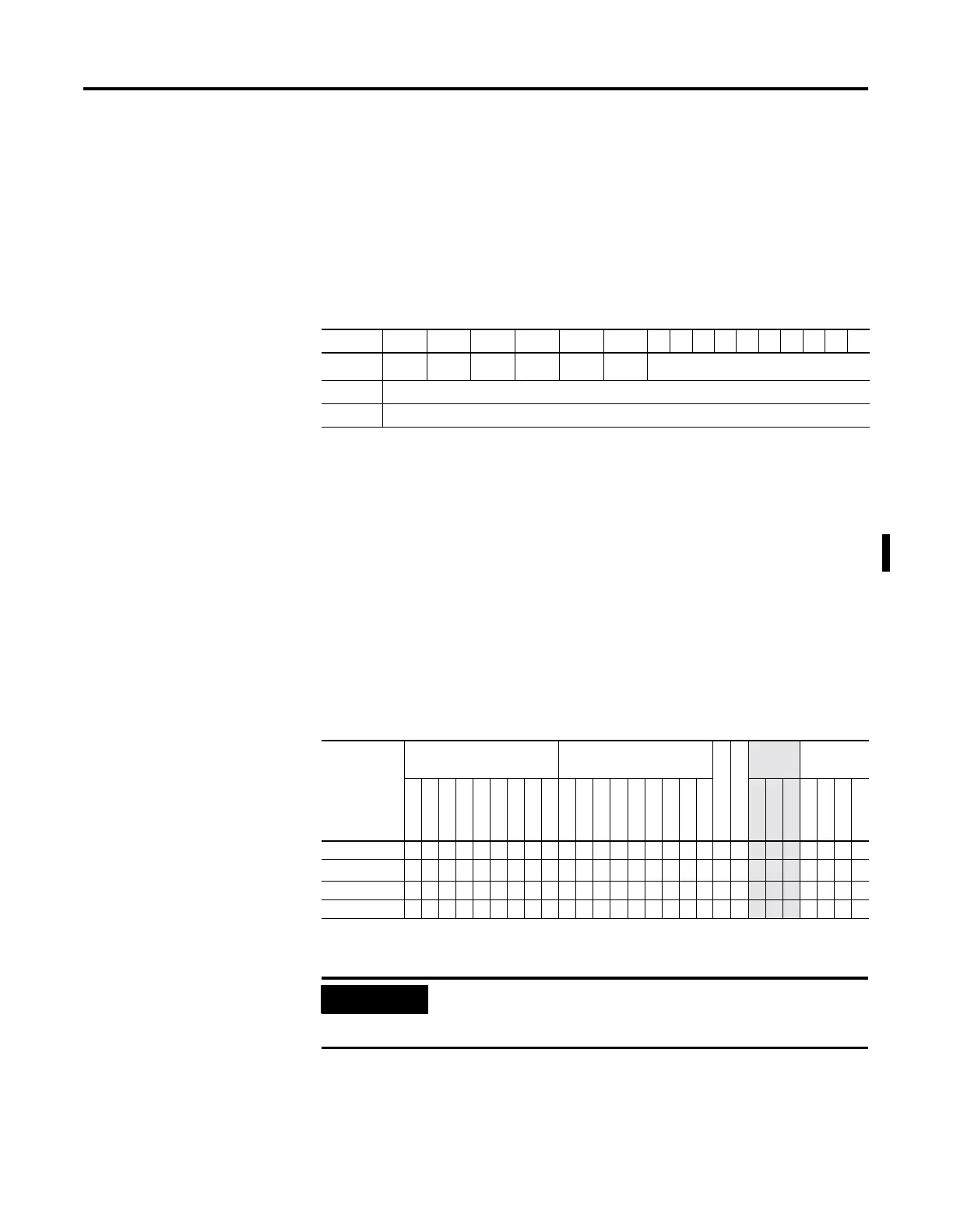
15 14 13 12 11 10 9876543210
Word 0
EN
(1)
(1) EN - Enable Bit is set on false-to-true transition of the rung and indicates the instruction is enabled.
--
DN
(2)
(2) DN - Done Bit, when set, indicates that the bit array has shifted one position.
--
ER
(3)
(3) ER - Error Bit, when set, indicates that the instruction detected an error such as entering a negative number for the
length or source operand.
UL
(4)
(4) UL - Unload Bit is the instruction’s output. Avoid using the UL (unload) bit when the ER (error) bit is set.
not used
Word 1 Size of bit array (number of bits).
Word 2 not used
Table 14.7 BSL Instruction Valid Addressing Modes and File Types
For definitions of the terms used in this table see Using the Instruction Descriptions on page4-2.
Parameter
Data Files Function Files
CS - Comms
IOS - I/O
Address
Mode
(1)
(1) See Important note about indirect addressing.
Address
Level
O
I
S
B
T, C, R
N
ST
L
MG, PD
RTC
HSC
PTO, PWM
STI
EII
BHI
MMI
DAT
TPI
Immediate
Direct
Indirect
Bit
Word
Long Word
Element
File ••••• • •••
Control
(2)
(2) Control file only. Not valid for Timers and Counters.
• •
Length
• •
Source •• ••• •
• ••
IMPORTANT
You cannot use indirect addressing with: S, ST, MG, PD,
RTC, HSC, PTO, PWM, STI, EII, BHI, MMI, DATI, TPI, CS,
IOS, and DLS files.

 Loading...


