Publication 1762-RM001C-EN-P
14-18 File Instructions
This instruction uses the following operands:
•
LIFO - The LIFO operand is the starting address of the stack.
•
Destination - The destination operand is a word or long word address
that stores the value which exits from the LIFO stack. The LFU
instruction unloads this value from the last location on the LIFO stack
and places it in the destination address. The address level of the
destination must match the LIFO stack. If LIFO is a word size file,
destination must be a word size file. If LIFO is a long word size file,
destination must be a long word size file.
•
Control - This is a control file address. The status bits, stack length,
and the position value are stored in this element. The control element
consists of 3 words:
•
Length - The length operand contains the number of elements in the
LIFO stack. The length of the stack can range from 1 to 128 (word) or
1 to 64 (long word).
•
Position - This is the next location in the LIFO stack where data will
be unloaded. Position is a component of the control register. The
position can range from 0 to 127 (word) or 0 to 63 (long word). The
position is decremented after each unload.
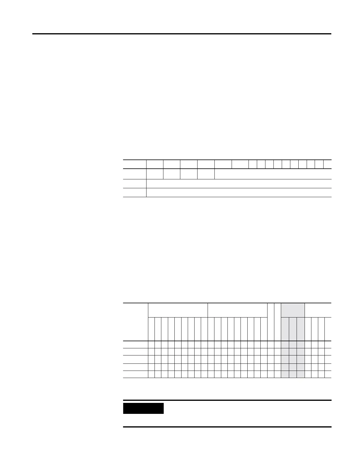
15 14 13 12 11 10 9 8 7 6 5 4 3 2 1 0
Word 0 --
EU
(1)
(1) EU - Enable Unload Bit is set on false-to-true transition of the rung and indicates the instruction is enabled.
DN
(2)
(2) DN - Done Bit, when set, indicates that the stack is full.
EM
(3)
(3) EM - Empty Bit, when set, indicates LIFO is empty.
not used
Word 1 Length - maximum number of words or double words in the stack.
Word 2 Position - the next available location where the instruction unloads data.
Table 14.17 LFU Instruction Valid Addressing Modes and File Types
For definitions of the terms used in this table see Using the Instruction Descriptions on page4-2.
Parameter
Data Files Function Files
CS - Comms
IOS - I/O
Address
Mode
(1)
(1) See Important note about indirect addressing.
Address
Level
O
I
S
B
T, C, R
N
ST
L
MG, PD
RTC
HSC
PTO, PWM
STI
EII
BHI
MMI
DAT
TPI
Immediate
Direct
Indirect
Bit
Word
Long Word
Element
LIFO ••••• • •••
Destination •• ••• •
• •••
Control
(2)
(2) Control file only. Not valid for Timers and Counters.
• •
Length
• •
Position
• •
IMPORTANT
You cannot use indirect addressing with: S, ST, MG, PD,
RTC, HSC, PTO, PWM, STI, EII, BHI, MMI, DAT, TPI, CS,
IOS, and DLS files.

 Loading...


