EasyManuals Logo

Allen-Bradley MicroLogix 1200 Reference Manual

Allen-Bradley MicroLogix 1200
424 pages
To Next Page IconTo Next Page
To Previous Page IconTo Previous Page
Page #203 background imageLoading...
Page #203 background image
Publication 1762-RM001C-EN-P
Sequencer Instructions 15-3
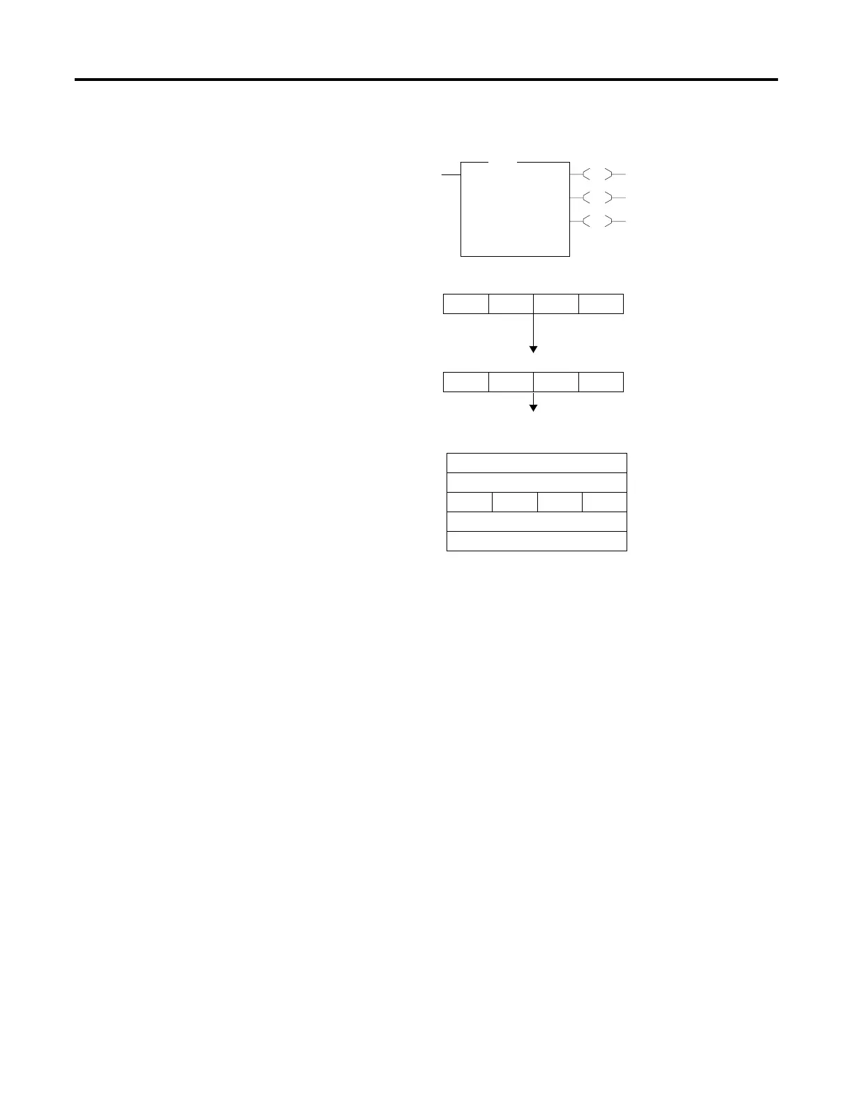
The following figure explains how the SQC instruction works.
SQC FD bit is set when the instruction detects that an input word matches
(through mask) its corresponding reference word.
The FD bit R6:21/FD is set in the example, since the input word matches
the sequencer reference value using the mask value.
EN
DN
FD
SQC
Sequencer Compare
File #B10:11
Mask FFF0
Source I:3.0
Control R6:21
Length 4<
Position 2<
SQC
Input Word I:3.0
0010 0100 1001 1101
Mask Value FFF0
1111 1111 1111 0000
Sequencer Ref File #B10:11
Word Step
B10:11 0
B10:12 1
B10:13 0010 0100 1001 0000 2
B10:14 3
B10:15 4

Table of Contents

Other manuals for Allen-Bradley MicroLogix 1200

Questions and Answers:

Question and Answer IconNeed help?

Do you have a question about the Allen-Bradley MicroLogix 1200 and is the answer not in the manual?

Allen-Bradley MicroLogix 1200 Specifications

General IconGeneral
SeriesMicroLogix 1200
TypeProgrammable Logic Controller (PLC)
MountingDIN rail or panel mount
Programming LanguageLadder Logic
Programming SoftwareRSLogix 500
I/O PointsUp to 40
Communication PortsRS-232, RS-485
Memory6 KB user memory
Power Supply24V DC or 120/240V AC
ExpansionSupports expansion I/O modules
Operating Temperature0°C to 55°C (32°F to 131°F)
Dimensions90 mm x 110 mm
Weight0.5 kg (1.1 lbs)

Related product manuals