Publication 1762-RM001C-EN-P
17-2 Input and Output Instructions
The IIM instruction allows you to selectively update input data without
waiting for the automatic input scan. This instruction uses the following
operands:
•
Slot - This operand defines the location where data is obtained for
updating the input file. The location specifies the slot number and the
word where data is to be obtained. For example, if slot = I:0, input
data from slot 0 starting at word 0 is masked and placed in input data
file I:0 starting at word 0 for the specified length. If slot = I0.1, word 1
of slot 0 is used, and so on.
•
Mask - The mask is a hex constant or register address containing the
mask value to be applied to the slot. If a given bit position in the
mask is a “1”, the corresponding bit data from slot is passed to the
input data file. A “0” prohibits corresponding bit data in slot from
being passed to the input data file. The mask value can range from 0
to 0xFFFF.
•
Length - This is the number of masked words to transfer to the input
data file.
Addressing Modes and File Types can be used as shown below:
IMPORTANT
Slot 0 is the only valid slot number that can be used
with this instruction. IIM cannot be used with
expansion I/O.
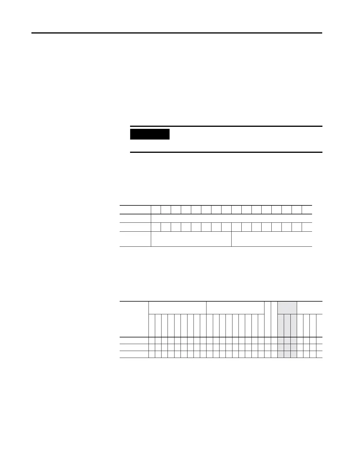
Bit 1514131211109876543210
Real Input Input Word
Mask 0000000011111111
Input Data
File
Data is Not Updated Updated to Match Input Word
Table 17.2 IIM Instruction Valid Addressing Modes and File Types
For definitions of the terms used in this table see Using the Instruction Descriptions on page4-2.
Parameter
Data Files Function Files
CS - Comms
IOS - I/O
Address
Mode
Address
Level
O
I
S
B
T, C, R
N
ST
L
MG, PD
RTC
HSC
PTO, PWM
STI
EII
BHI
MMI
DAT
TPI
Immediate
Direct
Indirect
Bit
Word
Long Word
Element
Slot • • •
Mask •• •••
• • ••
Length
•

 Loading...


