Publication 1762-RM001C-EN-P
20-24 ASCII Instructions
•
Characters Read (POS) is the number of characters that the
controller moved from the buffer to the string (0 to 82). This field is
read-only and resides in word 2 of the control data file.
•
Error displays the hexadecimal error code that indicates why the ER
bit was set in the control data file. See page 20-30 for error code
descriptions.
Addressing Modes and File Types can be used as shown below:
Instruction Operation
When the rung goes from false-to-true, the control element Enable (EN)
bit is set. When the instruction is placed in the ASCII queue, the Queue
bit (EU) is set. The Running bit (RN) is set when the instruction is
executing. The DN bit is set on completion of the instruction.
Once the requested number of characters are in the buffer, all characters
(including the Termination characters) are moved to the destination string.
The number of characters moved is stored in the POS word of the control
data file. The number in the Characters Read field is continuously updated
and the Done bit (DN) is not set until all of the characters have been read.
Exception: If the controller finds termination characters before done
reading, the Done bit (DN) is set and the number of characters found is
stored in the POS word of the control data file.
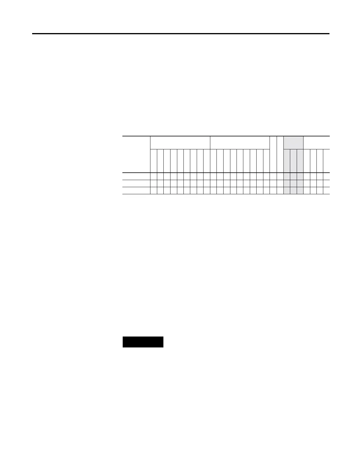
Table 20.26 ARL Instruction Valid Addressing Modes and File Types
For definitions of the terms used in this table see Using the Instruction Descriptions on page4-2.
Parameter
Data Files
(1)
(1) The Control data file is the only valid file type for the Control Element.
Function Files
CS - Comms
IOS - I/O
Address
Mode
Address
Level
O
I
S
B
T, C, R
N
ST
L
MG, PD
RTC
HSC
PTO, PWM
STI
EII
BHI
MMI
DAT
TPI
Immediate
Direct
Indirect
Bit
Word
Long Word
Element
Channel • •
Destination •
• •
Control •
• •
NOTE
For information on the timing of this instruction, see the
timing diagram on page 20-28.

 Loading...


