Publication 1762-RM001C-EN-P
Communications Instructions 21-15
Enabled and Waiting (EW)
The Enabled and Waiting Bit (EW) is set after the enable bit is set and the
message is in the buffer (not in the queue) and waiting to be sent. The
EW bit is cleared after the message has been sent and the processor
receives acknowledgement (ACK) from the target device. This is before
the target device has processed the message and sent a reply.
Error (ER)
The Error Bit (ER) is set when message transmission has failed. An error
code is written to the MSG File. The ER bit and the error code are cleared
the next time the associated rung goes from false to true.
Done (DN)
The Done Bit (DN) is set when the message is transmitted successfully.
The DN bit is cleared the next time the associated rung goes from false to
true.
Start (ST)
The Start Bit (ST) is set when the processor receives acknowledgment
(ACK) from the target device. The ST bit is cleared when the DN, ER, or
TO bit is set.
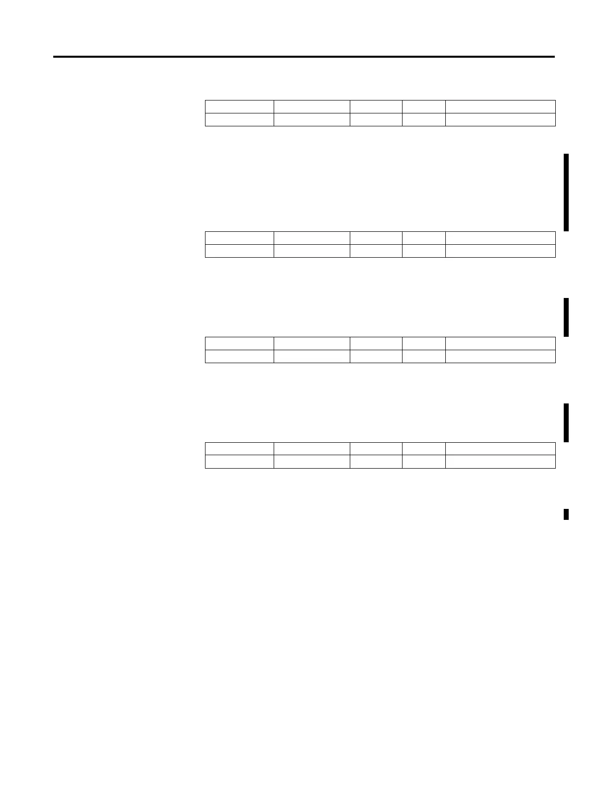
Address Data Format Range Type User Program Access
MG11:0/EW Binary On or Off Status Read Only
Address Data Format Range Type User Program Access
MG11:0/ER Binary On or Off Status Read Only
Address Data Format Range Type User Program Access
MG11:0/DN Binary On or Off Status Read Only
Address Data Format Range Type User Program Access
MG11:0/ST Binary On or Off Status Read Only

 Loading...


