Publication 1762-RM001C-EN-P
3-14 Function Files
Diagnostic Counter Blocks are shown for:
•
DH-485
•
DF1 Full-Duplex
•
DF1 Half-Duplex Slave
•
Modbus™ RTU Slave
•
ASCII
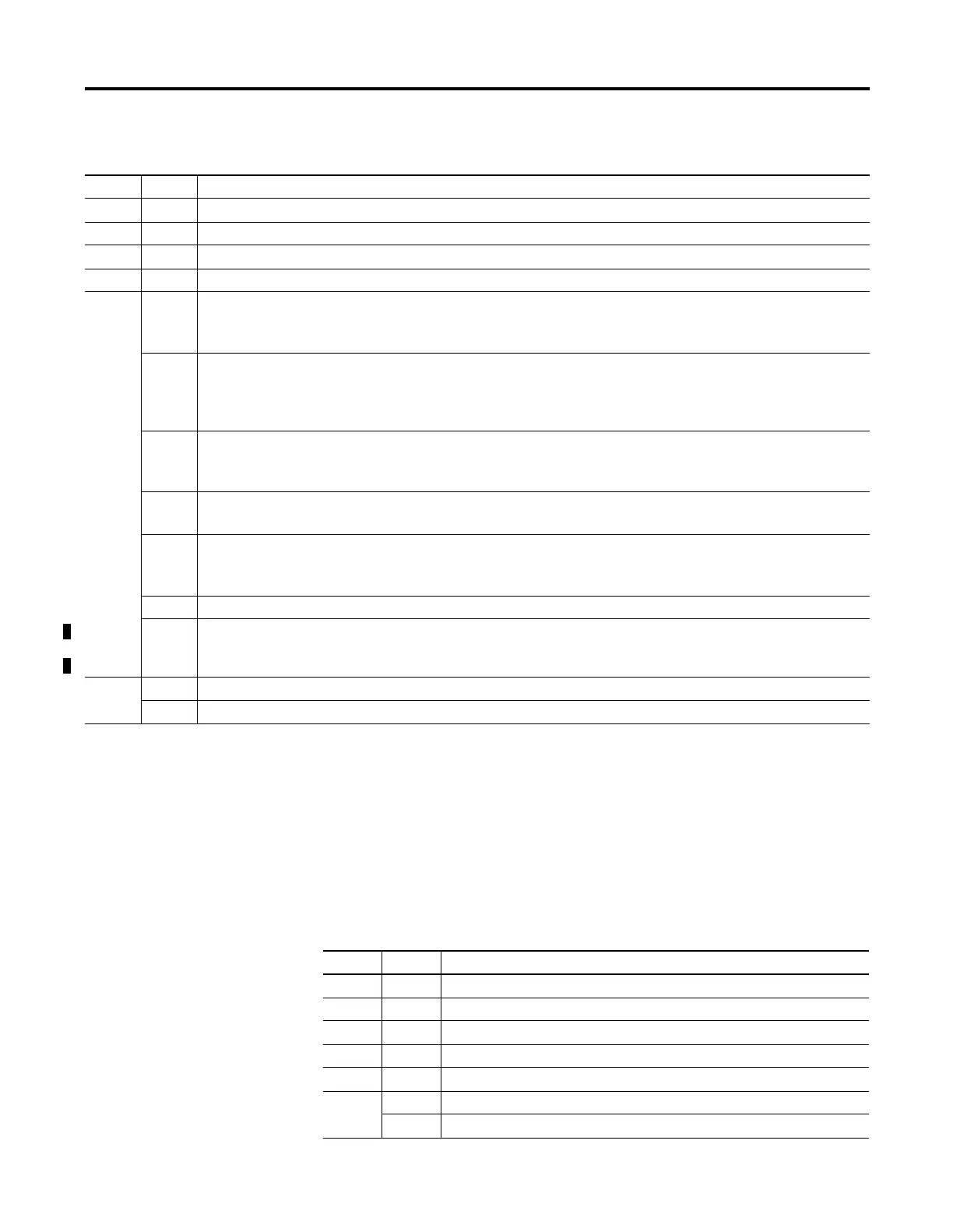
Table 3.11 General Channel Status Block
Word Bit Description
0 - Communications Channel General Status Information Category Identifier Code
1- Length
2- Format Code
3 - Communications Configuration Error Code
40ICP – Incoming Command Pending Bit
This bit is set (1) when the controller determines that another device has requested information from this controller.
Once the request has been satisfied, the bit is cleared (0).
1MRP – Incoming Message Reply Pending Bit
This bit is set (1) when the controller determines that another device has supplied the information requested by a MSG
instruction executed by this controller. When the appropriate MSG instruction is serviced (during end-of-scan, SVC, or
REF), this bit is cleared (0).
2MCP – Outgoing Message Command Pending Bit
This bit is set (1) when the controller has one or more MSG instructions enabled and in the communication queue. This
bit is cleared (0) when the queue is empty.
3 SSB – Selection Status Bit
This bit indicates that the controller is in the System Mode. It is always set.
4CAB – Communications Active Bit
This bit is set (1) when at least one other device is on the DH-485 network. If no other devices are on the network, this
bit is cleared (0).
5 to 14 Reserved
15 Communications Toggle Push Button Communications Defaults Active. This bit is set (1) whenever Channel 0 is in the
default communications mode. The bit is cleared (0) when Channel 0 is in user configured communications mode.
(Always 0 for 1764-LRP Processor Channel 1) This bit is not available with the Series A controllers.
5 0 to 7 Node Address - This byte value contains the node address of your controller on the network.
8 to 15 Baud Rate - This byte value contains the baud rate of the controller on the network.
Table 3.12 DH-485 Diagnostic Counters Block
Word Bit Description
6 - Diagnostic Counters Category Identifier Code (always 2)
7 - Length (always 30)
8 - Format Code (always 0)
9 - Total Message Packets Received
10 - Total Message Packets Sent
11 0 to 7 Message Packet Retries
8 to 15 Retry Limit Exceeded (Non-Delivery)

 Loading...


