MicroLogix 1762-IF4 Analog Input Module 9
Publication 1762-IN012C-EN-P - June 2013
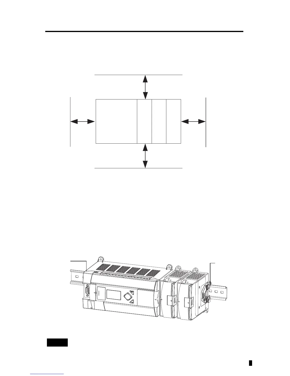
Module Spacing
Maintain spacing from objects such as enclosure walls, wireways and adjacent equipment. Allow
50.8 mm (2 in.) of space on all sides for adequate ventilation, as shown:
DIN Rail Mounting
The module can be mounted using the following DIN rails: 35 x 7.5 mm (EN 50 022 - 35 x 7.5)
or 35 x 15 mm (EN 50 022 - 35 x 15).
Before mounting the module on a DIN rail, close the DIN rail latch. Press the DIN rail
mounting area of the module against the DIN rail. The latch will momentarily open and lock
into place.
Use DIN rail end anchors (Allen-Bradley part number 1492-EA35 or 1492-EAH35) for
vibration or shock environments.
For environments with greater vibration and shock concerns, use the panel
mounting method described below, instead of DIN rail mounting.
MicroLogix
1100/1200/1400
1762 I/O
1762 I/O
1762 I/O
45159
End anchor
End anchor

 Loading...


