122 Rockwell Automation Publication 750-IN001O-EN-P - October 2014
Chapter 3 Lift and Mount the Drive
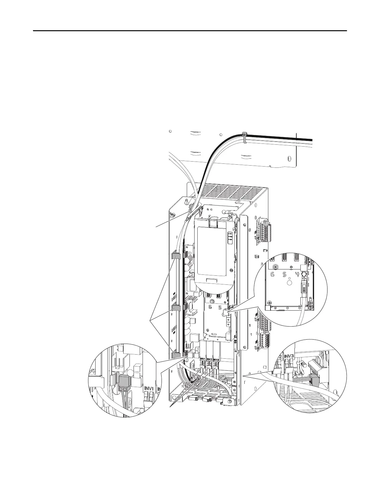
2. Disconnect the HIM cable ➊.
3. Disconnect the 24V wire harness ➋ from TB1 and P14 on the fiber
interface board.
4. Disconnect any fiber-optic cables ➌ from the fiber interface board. This
step is not necessary on Frame 8 drives.
5. Unlock the three cable supports ➍ along the left inside wall of the drive
control pod.
6. Open the releasable cable tie ➎ at the top of the drive control pod.
7. Without bending the cables to a radius less than 50 mm (2 in.), lift the
24V wire harness and fiber-optic cables out of the drive control pod.
Support the cable bundle so it is out of the way of the drive assembly when
it is rolled out of the cabinet.
➌
➊
➍
➎
➋
TB1
➋
P14
 Loading...


