Rockwell Automation Publication 750-IN001O-EN-P - October 2014 151
Power Wiring Chapter 4
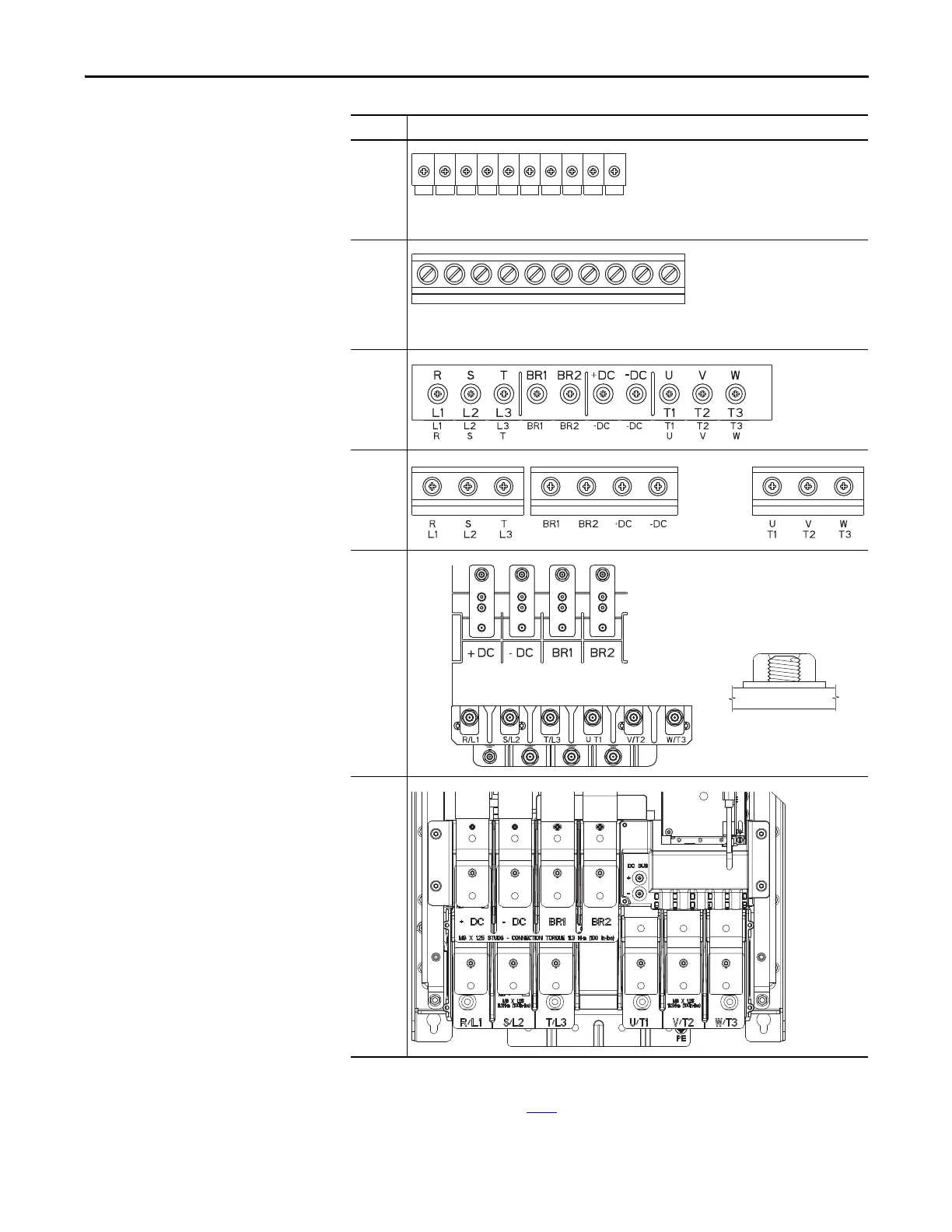
Wall Mount Frames 1…7 AC
Input Power Terminals
Frame Power Terminal Blocks
1
2
3
4
5
6
(1) (2)
(1) DC Bus Terminals are optional on Frame 6 and 7 drives: catalog number position 5 or install kit number 20-750-DCBB1-F6 (Frame 6)
or 20-750-DCBB1-F7 (Frame 7).
Dynamic Brake Resistor Terminals are optional on Frame 6 and 7 drives: catalog number position 12.
Refer to Catalog Number Explanation on page 13
.
(2) If the use of two conductors is desired, an AC Terminal Extension Kit (20-750-ACTE-F6) is available for Frame 6 drives.
When nuts are fully seated on the
Frame 6 power terminals, the stud
will not extend beyond the top edge
of the nut. Thread engagement is
sufficient for a secure connection.
7
(1)
L1
R
L2
S
L3
T
BR
1
BR
2
+
DC
-
DC
T1
U
T2
V
T3
W
L1
R
L2
S
L3
T
BR
1
BR
2
+
DC
-
DC
T1
U
T2
V
T3
W
 Loading...


