150 Rockwell Automation Publication 750-IN001O-EN-P - October 2014
Chapter 4 Power Wiring
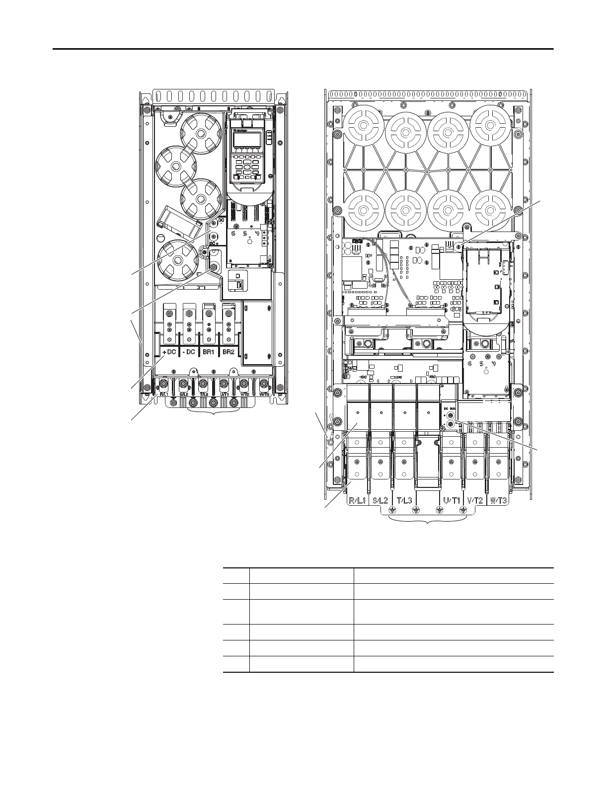
Figure 89 - Wall Mount Frames 6 and 7 Power Terminal and Termination Point Locations
➌
➎
➍
➊
➋
➋
➊
➌
➎
➍
➍
Wall Mount Frame 6
Wall Mount Frame 7
400/480V drives shown.
No. Name Description
➊ Power Terminals R/L1, S/L2, T/L3, U/T1, V/T2, W/T3
➋ PE Grounding Studs Terminating point to chassis ground for incoming AC line and motor
shield.
➌ DC Bus and Brake Terminals +DC, -DC, BR1, BR2 (Optional)
➍ PE-A and PE-B MOV and CMC Jumpers
➎ DC+ and DC- Bus Voltage Test Points
 Loading...


