Rockwell Automation Publication 750-IN001O-EN-P - October 2014 209
Power Wiring Chapter 4
Drive Power Jumper
Configuration
PowerFlex 750-Series drives contain protective MOVs and common mode
capacitors that are referenced to ground. To guard against drive damage and/or
operation problems, these devices must be properly configured according to
Tab l e 29
.
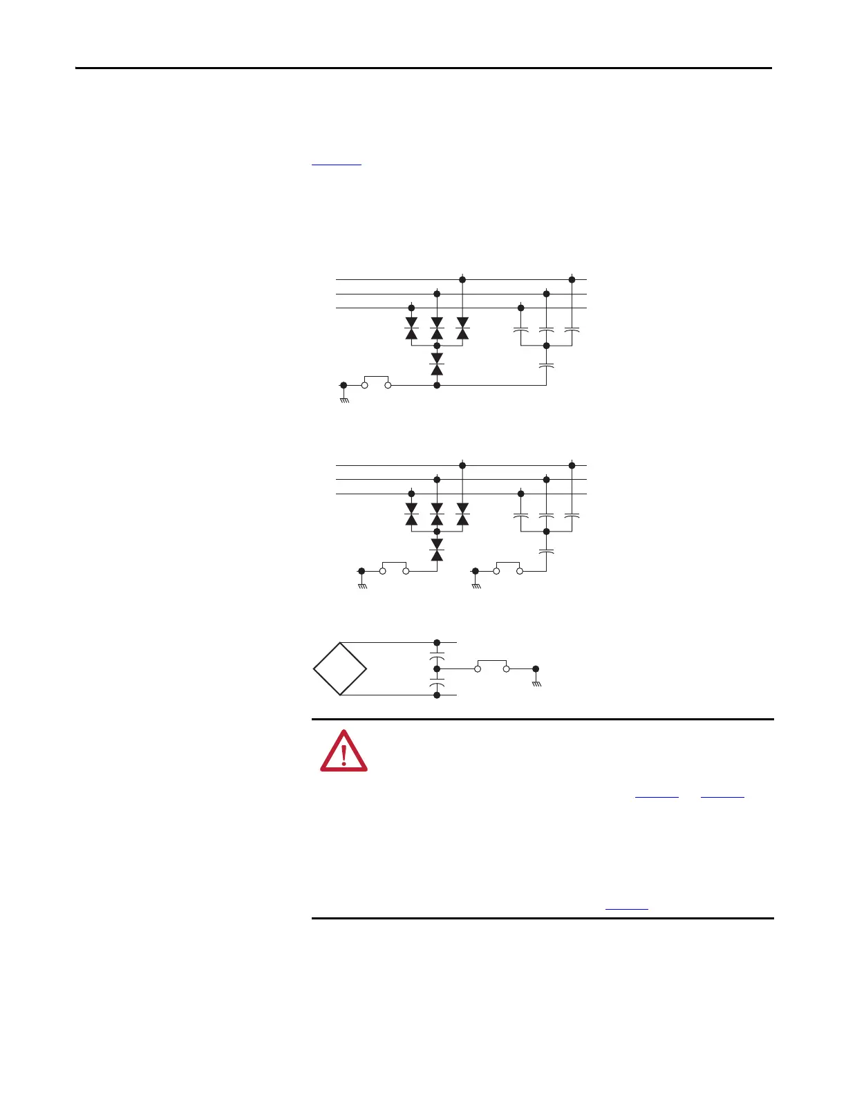
MOV, AC EMI Capacitor, and Common Mode Capacitor Circuits
Figure 111 - MOV and AC EMI Capacitor Phase to Ground (Wall Mount Frames 1…7)
Figure 112 - MOV and AC EMI Capacitor Phase to Ground (Floor Mount Frames 8…10) AC Input
Only
Figure 113 - Common Mode Capacitors to Ground (All Frames)
ATTENTION: To avoid an electric shock hazard, verify that the voltage on the
bus capacitors has discharged completely before servicing.
Frames 1…7: Measure the DC bus voltage at the power terminal block by
measuring between the +DC and -DC terminals (see Figure 88
and Figure 89 for
location) or between the +DC and -DC test point sockets if equipped. Also measure
between the +DC terminal or test point and the chassis, and between the -DC
terminal or testpoint and the chassis. The voltage must be zero for all three
measurements.
Frames 8…10: Measure the DC bus voltage at the DC+ and DC- TESTPOINT
sockets on the front of the power module (see Figure 92
for location).
R/L1
S/L2
T/L3
1
23 4
PE–A
1
23 4
R/L1
S/L2
T/L3
1
23 4
PE–A1
1
23 4
PE–A2
DC+
DC–
PE–B
 Loading...


