1-10 Installation/Wiring
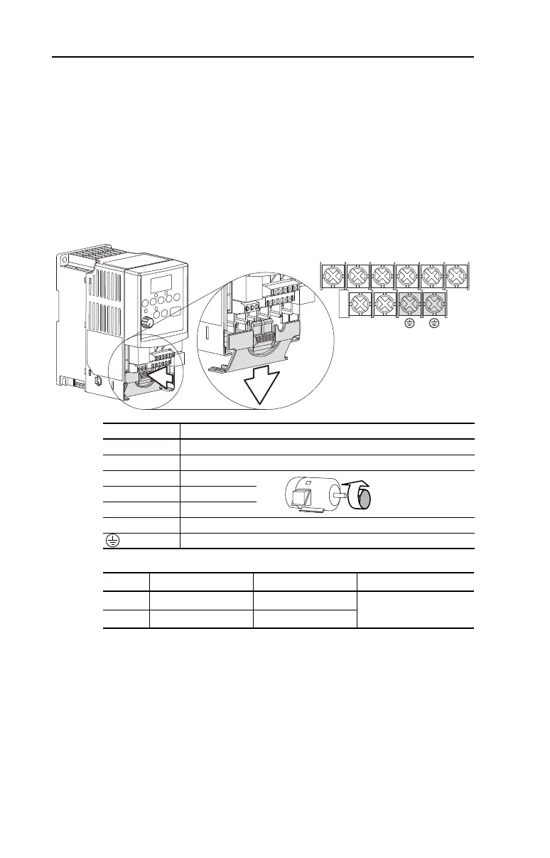
Power Terminal Block
The drive utilizes a finger guard over the power wiring terminals. To
remove:
1. Press in and hold the locking tab.
2. Slide finger guard down and out.
Replace the finger guard when wiring is complete.
Figure 1.4 Power Terminal Block (A Frame Shown)
Table 1.F Power Terminal Block Specifications
V/T2T/L3S/L2R/L1 U/T1 W/T3
BR+
BR-
Terminal Description
R/L1, S/L2 1-Phase Input
R/L1, S/L2, T/L3 3-Phase Input
U/T1 To Motor U/T1
=
Switch any two motor
leads to change
forward direction.
V/T2 To Motor V/T2
W/T3 To Motor W/T3
BR+, BR- Dynamic Brake Resistor Connection
Safety Ground - PE
Frame Maximum Wire Size
(1)
(1)
Maximum/minimum sizes that the terminal block will accept - these are not
recommendations.
Minimum Wire Size
(1)
Torque
A 3.3 mm
2
(12 AWG) 0.8 mm
2
(18 AWG)
1.7-2.2 N-m (16-19 lb.-in.)
B 5.3 mm
2
(10 AWG) 1.3 mm
2
(16 AWG)

 Loading...


