Process PI Loop 2-143
When PI Ramp Reference is selected in the PI Configuration
parameter, and PI is disabled, the value used for the PI reference will
be the PI feedback. This will cause PI error to be zero. Then when the
PI is enabled the value used for the PI reference will ramp to the
selected value for PI reference at the selected acceleration or
deceleration rate. After the PI reference reaches the selected value the
ramp is bypassed until the PI is disabled and enabled again. S-curve is
not available as part of the PI linear ramp.
• Zero Clamp - This feature limits the possible drive action to one
direction only. Output from the drive will be from zero to maximum
frequency forward or zero to maximum frequency reverse. This
removes the chance of doing a “plugging” type operation as an
attempt to bring the error to zero.
The PI has the option to limit operation so that the output frequency
will always have the same sign as the master speed reference. The
zero clamp option is selected in the PI Configuration parameter. Zero
clamp is disabled when PI has exclusive control of speed command.
For example, if master speed reference is +10 Hz and the output of
the PI results in a speed adder of –15 Hz, zero clamp would limit the
output frequency to not become less than zero. Likewise, if master
speed reference is –10 Hz and the output of the PI results in a speed
adder of +15 Hz, zero clamp would limit the output frequency to not
become greater than zero.
• Feedback Square Root - This feature uses the square root of the
feedback signal as the PI feedback. This is useful in processes that
control pressure, since centrifugal fans and pumps vary pressure with
the square of speed.
The PI has the option to take the square root of the selected feedback
signal. This is used to linearize the feedback when the transducer
produces the process variable squared. The result of the square root is
normalized back to full scale to provide a consistent range of
operation. The option to take the square root is selected in the PI
Configuration parameter.
• Stop Mode (PowerFlex 700 Only). When Stop Mode is set to “1”
and a Stop command is issued to the drive, the PI loop will continue
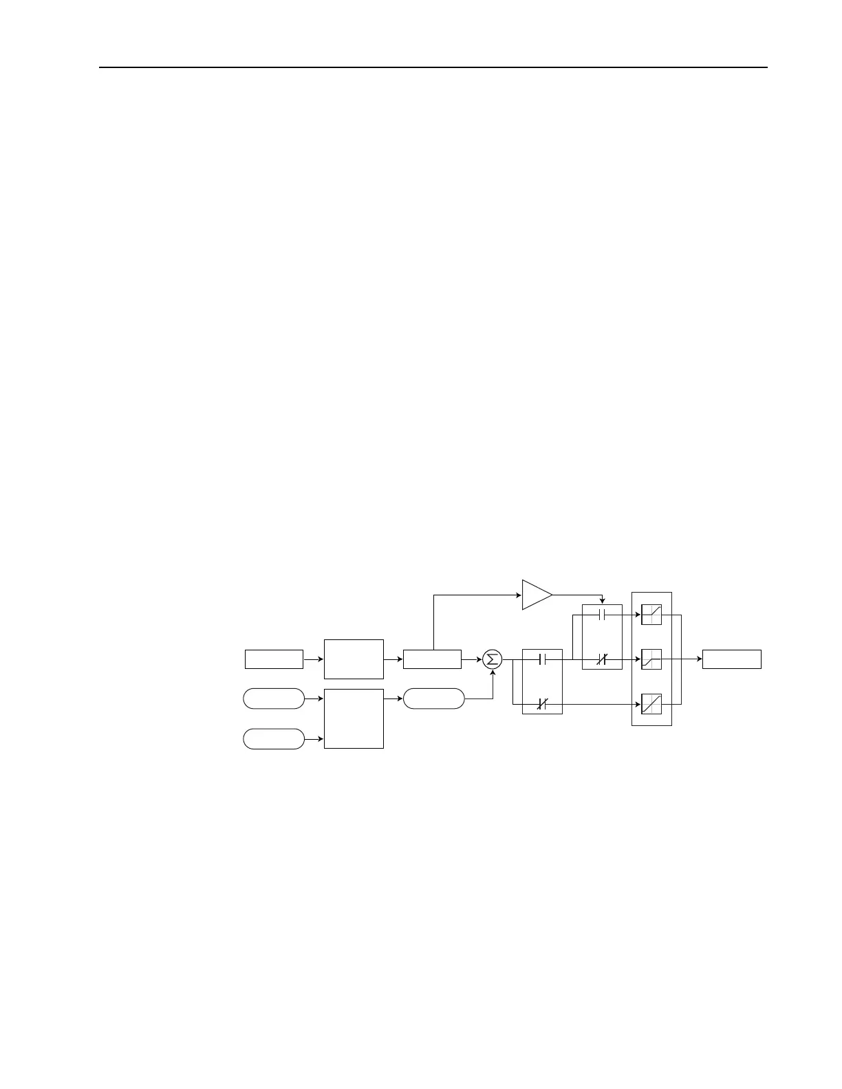
PI Output
Spd Ramp
+
+
PI_Config
.ZeroClamp
Spd Cmd
≥
0
+32K
-32K
+32K
-32K
0
0
Process PI
Controller
Linear
Ramp
& S-Curve
Spd Ref
PI Fbk
PI Ref
 Loading...


