Rockwell Automation Publication 20A-IN009E-EN-P - January 2015 9
PowerFlex 70 Adjustable Frequency AC Drive
Essential Requirements for CE Compliance
These eight conditions must be satisfied for PowerFlex drives to meet the
requirements of EN61800-3:
• Standard PowerFlex 70 CE compatible drive.
• Review important precautions/attention statements throughout this
manual before installing the drive.
• The drive installation cannot include the encoder interface option
(20A-ENC-1, drive catalog number, position 16 must be 0. For example:
20Axxxxxxxxx xxx0).
• Ground the drive as described in General Grounding Requirements on
page 22
.
• Output power, control (I/O), and signal wiring must be braided, shielded
cable with a coverage of 75% or better, metal conduit or equivalent
attenuation.
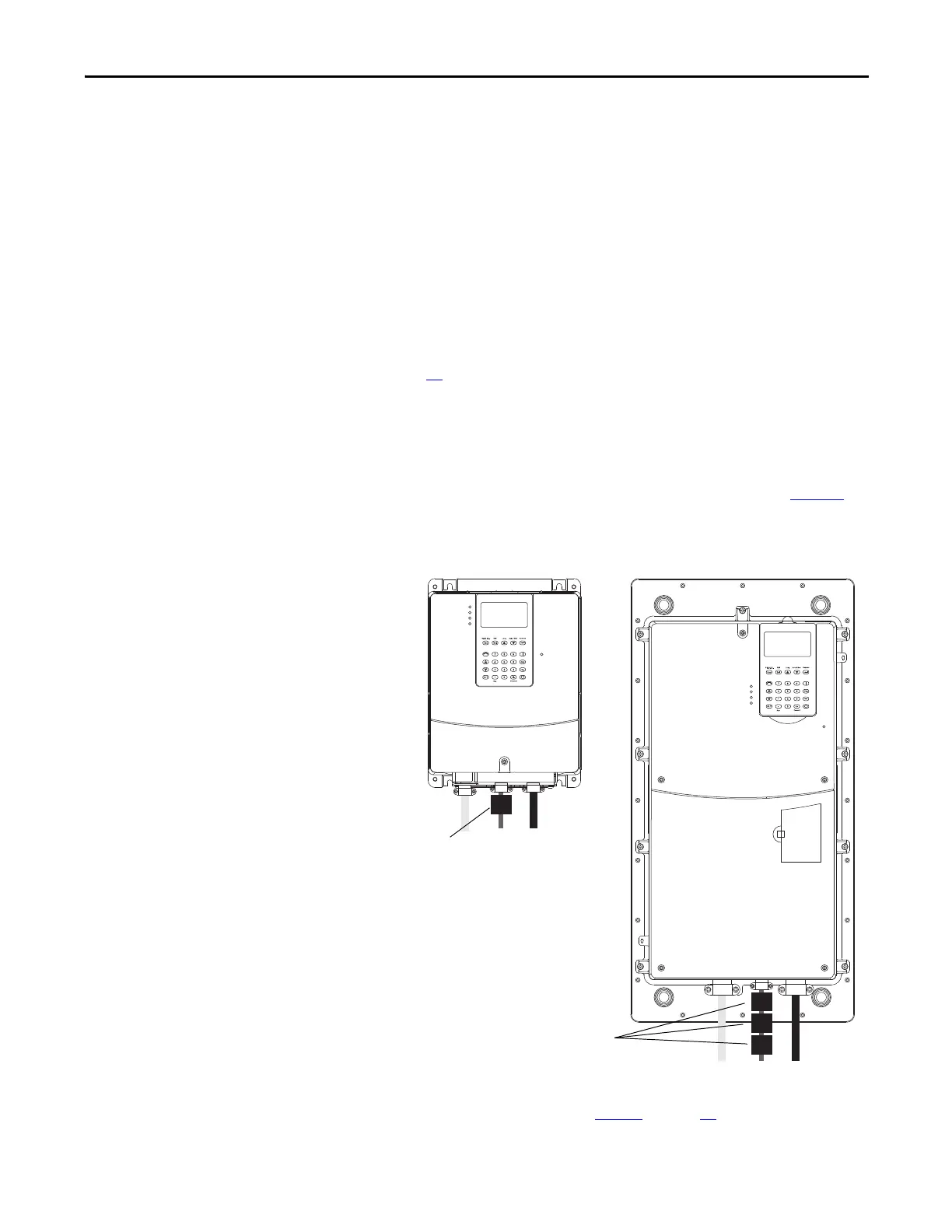
• For B and E frame drives only, ferrite core kit (20A-EMC01) must be
installed on the I/O cable, as close to the drive as possible, per Figure 1
.
Figure 1 - Ferrite Core Installation on B Frame and E Frame Drives Only
• All shielded cables must terminate with the proper shielded connector.
• Comply with the conditions in Ta bl e 1
on page 10.
B Frame
E Frame
Install One Ferrite
Core on the I/O Cable
for B Frame Drives
Install Three Ferrite
Cores on the I/O Cable
for E Frame Drives

 Loading...


