Rockwell Automation Publication 20A-UM001N-EN-P - July 2013 111
Application Notes Appendix C
Detailed Operation
Mode Description
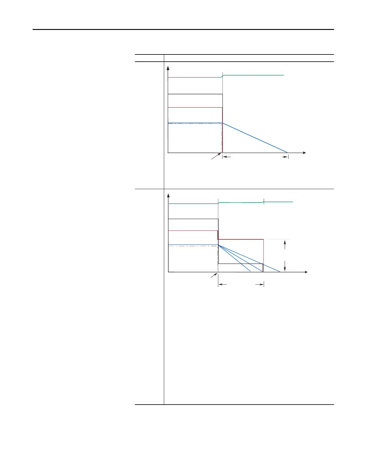
Coast to Stop
Coast is selected by setting [Stop Mode A/B] to a value of “0.” When in Coast to Stop, the drive
acknowledges the Stop command by shutting off the drive output and releasing control of the motor.
The load and motor coasts until the kinetic energy is dissipated.
DC Brake to
Stop
This method uses DC injection of the motor to Stop and/or hold the load. DC Brake is selected by
setting [Stop Mode A/B] to a value of “3.” The amount of time that braking is applied is programmed in
[DC Brake Time] and the magnitude of the current used for braking is programmed in and [DC Brake
Level]. This mode of braking generates up to 40% of rated motor torque for braking and is typically
used for low inertia loads with infrequent Stop cycles.
1. On Stop, 3 phase drive output goes to zero (off)
2. Drive outputs DC voltage on the last used phase at the level programmed in [DC Brake Level],
parameter 158. This voltage causes a “stopping” brake torque. If the voltage is applied for a time
that is longer than the actual possible stopping time, the remaining time is used to attempt to hold
the motor at zero speed (decel profile “B” on the diagram above).
3. DC voltage to the motor continues for the amount of time programmed in [DC Brake Time],
parameter 159. Braking ceases after this time expires.
4. After the DC Braking ceases, no further power is supplied to the motor. The motor/load may or may
not be stopped. The drive has released control of the motor/load (decel profile “A” on the diagram
above).
5. The motor, if rotating, coasts from its present speed for a time that is dependent on the remaining
kinetic energy and the mechanics of the system (inertia, friction, and so on).
6. Excess motor current and/or applied duration, could cause motor damage. The user is also
cautioned that motor voltage can exist long after the Stop command is issued. The right
combination of Brake Level and Brake Time must be determined to provide the safest, most
efficient stop (decel profile “C” on the diagram above).
Coast Time is load dependent
Stop
Command
Time
Output Voltage
Bus Voltage
Output Current
Motor Speed
Command Speed
Stop
Command
DC Brake Time
(A)(C)(B)
Time
Output Voltage
Output Current
Motor Speed
DC
Brake Level
Bus Voltage
Command Speed
 Loading...


