120 Rockwell Automation Publication 20A-UM001N-EN-P - July 2013
Appendix C Application Notes
If a digital input has been configured to “PI Enable,” two events are required to
enable the loop: the digital input must be closed AND bit 0 of the PI Control
parameter must be = 1.
If no digital input is configured to “PI Enable,” the Bit 0 = 1 condition must be
met. If the bit is permanently set to “1”, the loop is enabled as soon as the drive
goes into “run”.
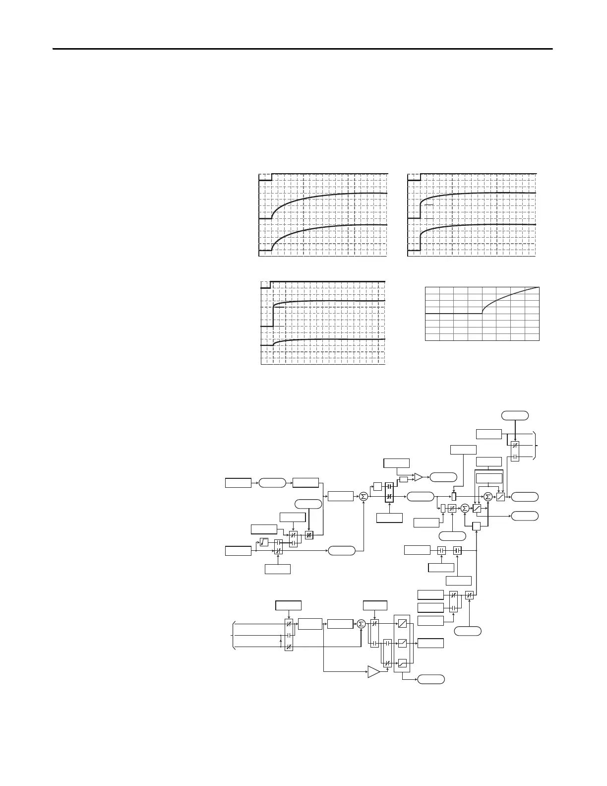
PI Enabled
Spd Cmd
PI Output
PI Pre-load Value
PI Pre-load Value = 0 PI Pre-load Value > 0
Pre-load to Command Speed
PI Enabled
Spd Cmd
PI Output
Start at Spd Cmd
-100.0 -75.0 -50.0 -25.0 0.0 25.0 50.0 75.0 100.0
Normalized Feedback
Normalized SQRT(Feedback)
-100.0
-75.0
-50.0
-25.0
0.0
25.0
50.0
75.0
100.0
+
+
+
+
z
-1
*
*
PI Fbk
PI Error
PI Output
PI Ref
PI Cmd
Linear
Ramp
-
+
-
In Limit
PI XS Error
abs
PI_Config
.Exclusive
Current Limit
or Volt Limit
Spd Cmd
*(PI Ref Sel)
*(PI Fbk Sel)
PI Kp
Spd Ref
PI Ki
PI Neg Limit
PI Pos Limit
PI_Status
.Hold
PI_Config
.RampCmd
PI_Status
.Enabled
PI_Config
.Invert
PI_Config
.Sqrt
0
PI ExcessErr
PI_Config
.PreloadCmd
Preload Value
PI_Status
.Enabled
Spd Cmd
PI_Status
.Enabled
to
A
Linear Ramp
& S-Curve
Spd Ramp
0
+
+
Zclamped
PI_Config
.Exclusive
PI_Config
.ZeroClamp
+32K
0
-32K
0
+32K
-32K
Spd Cmd
A
 Loading...


