16 PowerFlex 700 Adjustable Frequency AC Drive Quick Start
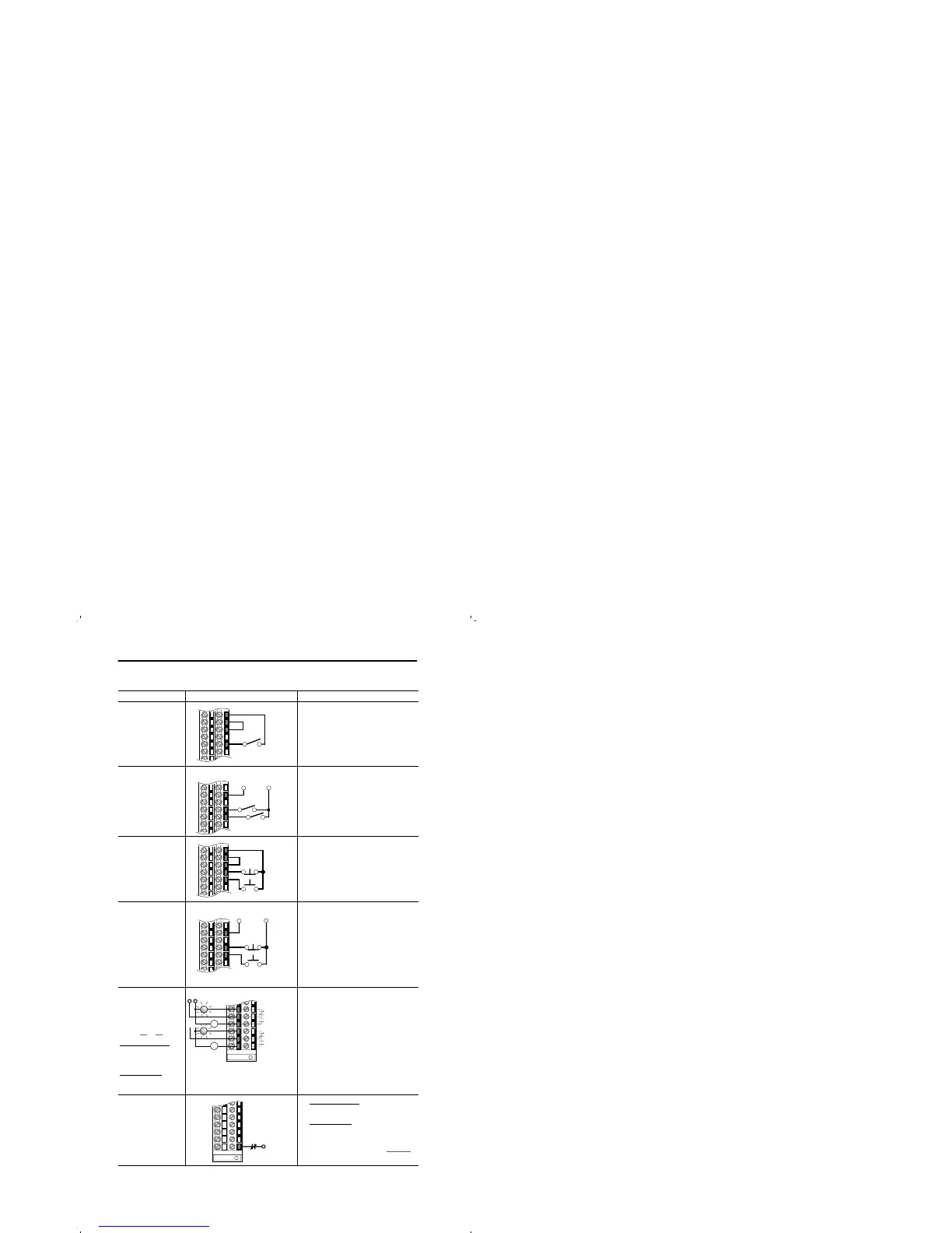
I/O Wiring Examples (continued)
Input/Output Connection Example Required Parameter Changes
2-Wire Control
Non-Reversing
(1)
24V DC internal
supply
• Disable Digital Input:#1:
Parameter 361 = “0, Unused”
• Set Digital Input #2:
Parameter 362 = “7, Run”
• Set Direction Mode:
Parameter 190 = “0, Unipolar”
2-Wire Control
Reversing
(1)
External supply
(I/O Board
dependent)
• Set Digital Input:#1:
Parameter 361 = “8, Run Forward”
• Set Digital Input #2:
Parameter 362 = “9, Run Reverse”
3-Wire Control
Internal supply
• No Changes Required
3-Wire Control
External supply
(I/O Board depen-
dent). Requires
3-wire functions only
([Digital In1 Sel]).
Using 2-wire selec-
tions will cause a type
2 alarm.
• No Changes Required
Digital Output
Relays shown in
powered state with
drive faulted. See
pages
12 & 14.
Standard Control
1 relay at terminals
14-16.
Vector Control
2 relays at terminals
14-16.
• Select Source to Activate:
Parameters 380/384
Enable Input •
Standard Control
Configure with parameter 366
• Vector Control
Configure with parameter 366
For dedicated hardware Enable:
Remove Jumper J10 (see page 13)
(1)
Important: Programming inputs for 2 wire control deactivates all HIM Start buttons.
24
25
26
28
Stop-Run
25
27
28
Run Rev.
Run Fwd.
115V/
+24V
Neutral/
Common
Start
24
25
26
27
28
Stop
Start
25
27
28
Stop
115V/
+24V
Neutral/
Common
Power Source
11
12
13
14
15
16
Fault
NOT Fault
NOT Run
Run
or
32

 Loading...


