10 PowerFlex 700 Adjustable Frequency AC Drive Quick Start
Table E Power Terminal Block Specifications
Name Frame Description
Wire Size Range
(1)
Torque
Maximum Minimum Maximum Recommended
Power Terminal
Block
0 & 1 Input power and
motor connections
4.0 mm
2
(10 AWG)
0.5 mm
2
(22 AWG)
1.7 N-m
(15 lb.-in.)
0.8 N-m
(7 lb.-in.)
2 Input power and
motor connections
10.0 mm
2
(6 AWG)
0.8 mm
2
(18 AWG)
1.7 N-m
(15 lb.-in.)
1.4 N-m
(12 lb.-in.)
3 Input power and
motor connections
25.0 mm
2
(3 AWG)
2.5 mm
2
(14 AWG)
3.6 N-m
(32 lb.-in.)
1.8 N-m
(16 lb.-in.)
BR1, 2 terminals 10.0 mm
2
(6 AWG)
0.8 mm
2
(18 AWG)
1.7 N-m
(15 lb.-in.)
1.4 N-m
(12 lb.-in.)
5
(75 HP)
Input power, BR1,
2, DC+, DC– and
motor connections
35.0 mm
2
(1/0 AWG)
2.5 mm
2
(14 AWG)
3.6 N-m
(32 lb.-in.)
3.6 N-m
(32 lb.-in.)
PE 35.0 mm
2
(1/0 AWG)
16.0 mm
2
(6 AWG)
5 N-m
(44 lb.-in.)
5 N-m
(44 lb.-in.)
5
(100
HP)
Input power, DC+,
DC– and motor
connections
70.0 mm
2
(3/0 AWG)
16.0 mm
2
(4 AWG)
15 N-m
(133 lb.-in.)
15 N-m
(133 lb.-in.)
BR1, 2, terminals 35.0 mm
2
(1/0 AWG)
2.5 mm
2
(14 AWG)
3.6 N-m
(32 lb.-in.)
3.6 N-m
(32 lb.-in.)
PE 35.0 mm
2
(1/0 AWG)
16.0 mm
2
(6 AWG)
5 N-m
(44 lb.-in.)
5 N-m
(44 lb.-in.)
AUX Terminal
Block
0-3 Auxiliary Control
Voltage
(2)
1.3 mm
2
(16 AWG)
0.2 mm
2
(24 AWG)
——
5 4.0 mm
2
(10 AWG)
0.5 mm
2
(22 AWG)
0.6 N-m
(5.3 lb.-in.)
0.6 N-m
(5.3 lb.-in.)
(1)
Maximum/minimum sizes that the terminal block will accept - these are not recommendations.
(2)
External control power:
UL Installation - 300V DC, ±10%, Non UL Installation - 270-600V DC, ±10%.
0-3 Frame - 40 W, 165 mA, 5 Frame - 80 W, 90 mA.
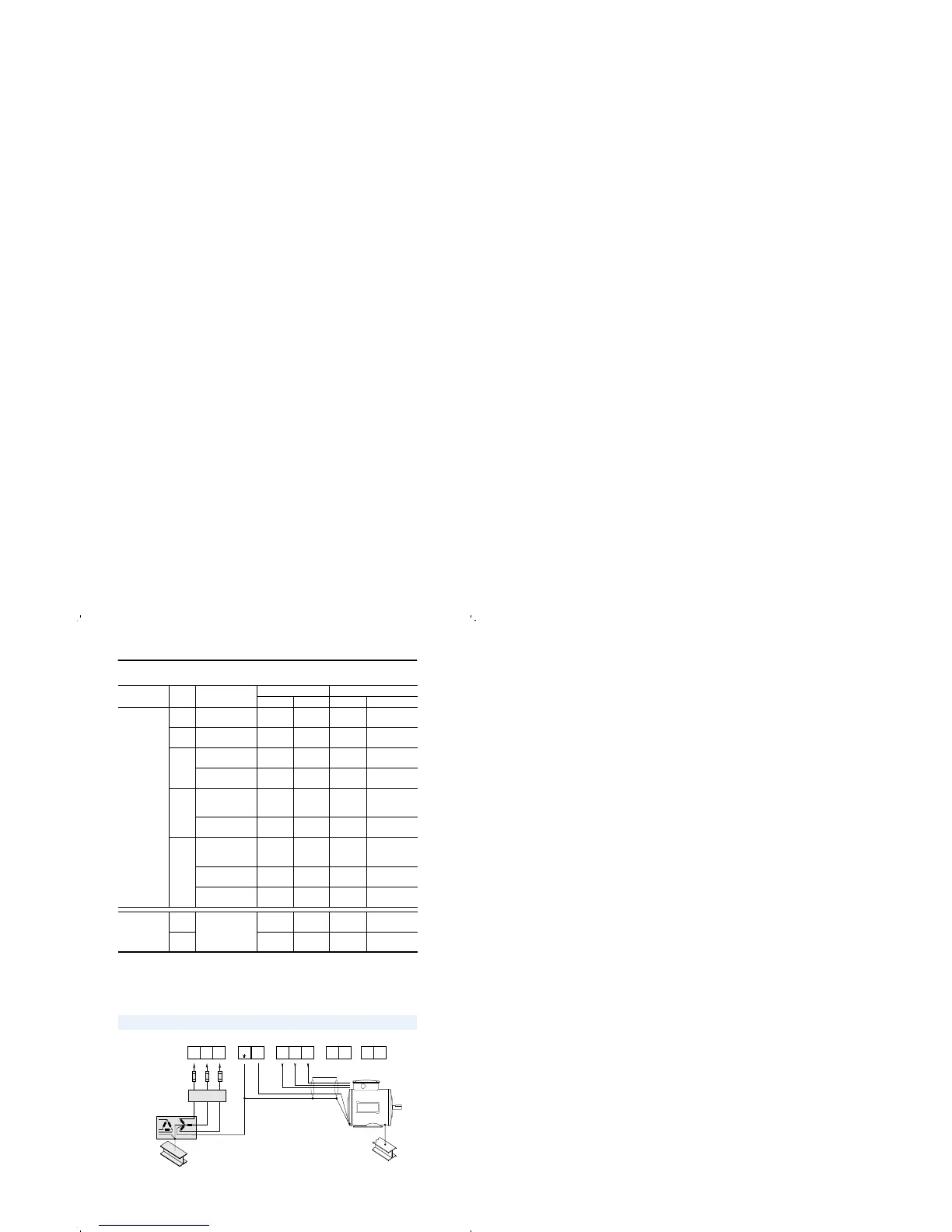
Power & Ground Wiring
PE
R
(L1)
S
(L2)
T
(L3)
U
(T1)
V
(T2)
W
(T3)
DC
+
DC
–
Required
Input Fusing
Required Branch
Circuit Disconnect
BR1 BR2

 Loading...


