PowerFlex 700 Adjustable Frequency AC Drive Quick Start 15
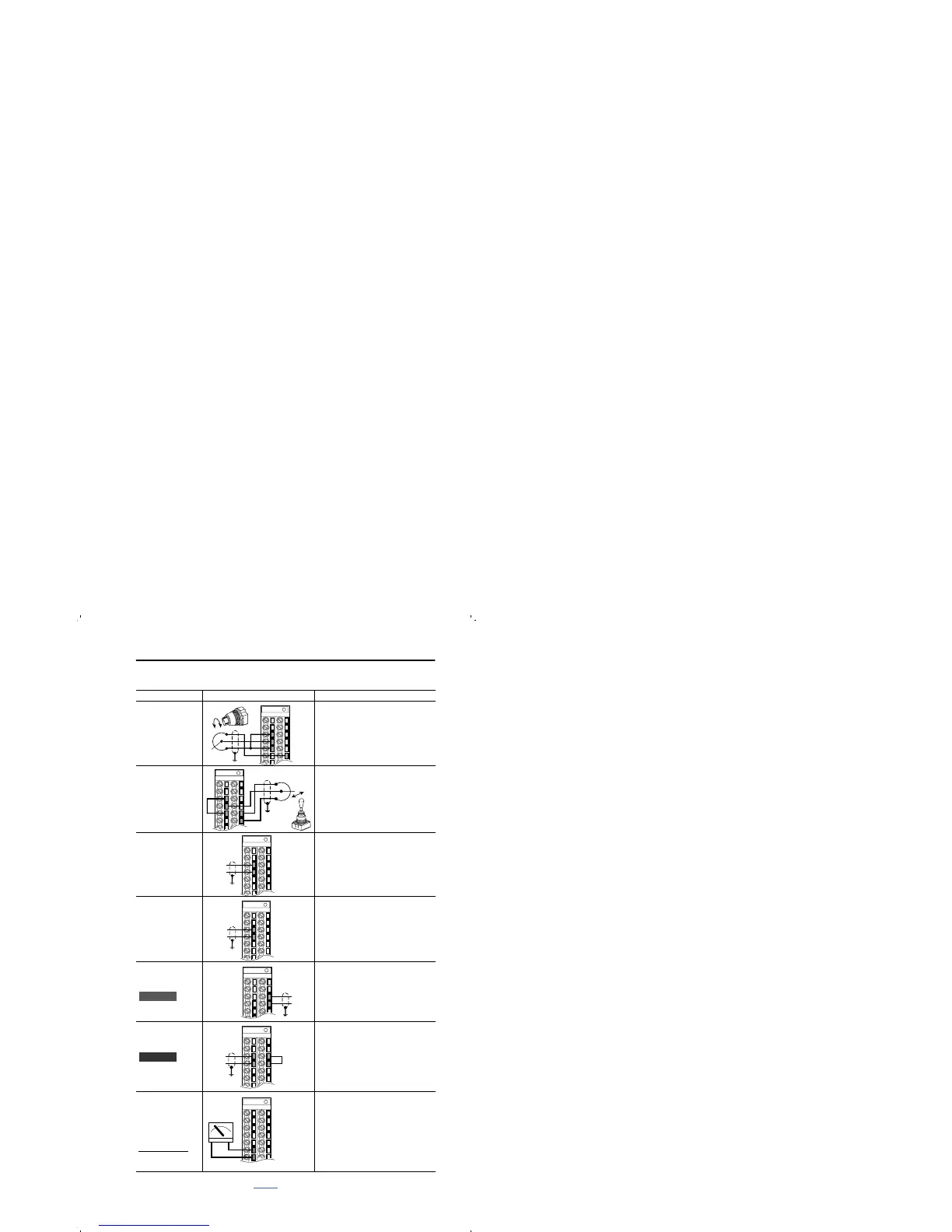
I/O Wiring Examples
Input/Output Connection Example Required Parameter Changes
Potentiometer
Unipolar Speed
Reference
(1)
10k Ohm Pot.
Recommended
(2k Ohm Minimum)
• Adjust Scaling:
Parameters 91/92 and 325/326
• View Results:
Parameter 002
Joystick Bipolar
Speed Reference
(1)
±10V Input
• Set Direction Mode:
Parameter 190 = “1, Bipolar”
• Adjust Scaling:
Parameters 91/92 and 325/326
• View Results:
Parameter 002
Analog Input
Bipolar Speed
Reference
±10V Input
• Set Direction Mode:
Parameter 190 = “1, Bipolar”
• Adjust Scaling:
Parameters 91/92 and 325/326
• View Results:
Parameter 002
Analog Voltage
Input Unipolar
Speed Reference
0 to +10V Input
• Configure Input with parameter 320
• Adjust Scaling:
Parameters 91/92 and 325/326
• View results:
Parameter 002
Analog Current
Input Unipolar
Speed Reference
4-20 mA Input
• Configure Input for Current:
Parameter 320, Bit 1 = “1, Current”
• Adjust Scaling:
Parameters 91/92 and 325/326
• View Results:
Parameter 002
Analog Current
Input Unipolar
Speed Reference
4-20 mA Input
• Configure Input for Current:
Parameter 320 and add jumper at
appropriate terminals
• Adjust Scaling:
Parameters 91/92 and 325/326
• View results:
Parameter 002
Analog Output
±10V, 4-20 mA
Bipolar
+10V Unipolar
(shown)
Standard Control
4-20 mA Unipolar
(use term. 8 & 9)
• Configure with Parameter 340
• Select Source Value:
Parameter 384, [Digital Out1 Sel]
• Adjust Scaling:
Parameters 343/344
(1)
Refer to the Attention statement on page 11 for important bipolar wiring information.
3
4
5
22
3
5
21
22
3
4
3
4
Standard
19
20
–
+
Vector
3
4
19
20
6
7
+–

 Loading...


