14 PowerFlex 700 Adjustable Frequency AC Drive Quick Start
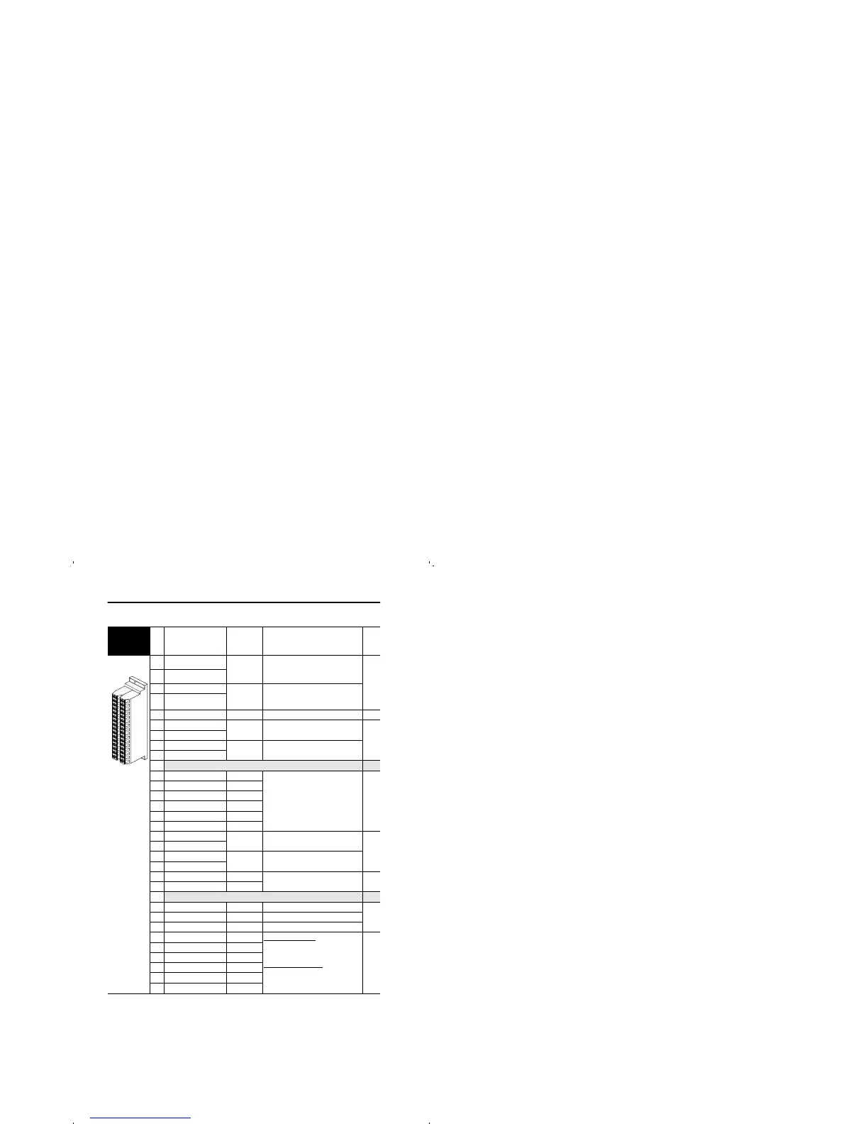
Figure 7 Standard Control Option I/O Terminal Designations
Standard
Control
Option
No. Signal
Factory
Default
Description
Related
Param.
1 Anlg Volts In 1 (–)
(2)
Isolated
(3)
, bipolar, differential,
±10V, 11 bit & sign, 88k ohm input
impedance.
320 -
327
2 Anlg Volts In 1 (+)
3 Anlg Volts In 2 (–)
(2)
Isolated
(4)
, bipolar, differential,
±10V, 11 bit & sign, 88k ohm input
impedance.
4 Anlg Volts In 2 (+)
5 Pot Common – For (+) and (–) 10V pot references.
6 Anlg Volts Out 1 (–)
(2)
Bipolar, ±10V, 11 bit &
sign, 2k ohm minimum load.
340 -
344
7 Anlg Volts Out 1 (+)
8 Anlg Current Out 1 (–)
(2)
4-20mA, 11 bit & sign, 400 ohm
maximum load.
9 Anlg Current Out 1 (+)
10
Reserved for Future Use
11 Digital Out 1 – N.C.
(1)
Fault Max. Resistive Load:
240V AC/30V DC – 1200VA, 150W
Max. Current: 5A, Min. Load: 10mA
Max. Inductive Load:
240V AC/30V DC – 840VA, 105W
Max. Current: 3.5A, Min. Load: 10mA
380 -
387
12 Digital Out 1 Common
13 Digital Out 1 – N.O.
(1)
NOT Fault
14 Digital Out 2 – N.C.
(1)
NOT Run
15 Digital Out 2 Common
16 Digital Out 2 – N.O.
(1)
Run
17 Anlg Current In 1 (–)
(2)
Isolated
(3)
,
4-20mA
, 11 bit & sign,
124 ohm input
impedance.
320 -
327
18 Anlg Current In 1 (+)
19 Anlg Current In 2 (–)
(2)
Isolated
(4)
, 4-20mA, 11 bit & sign,
124 ohm input impedance.
20 Anlg Current In 2 (+)
21 –10V Pot Reference – 2k ohm minimum.
22 +10V Pot Reference –
23 Reserved for Future Use
24 +24VDC
(5)
– Drive supplied logic input power.
(5)
25 Digital In Common –
26 24V Common
(5)
– Drive supplied logic input power.
(5)
27 Digital In 1 Stop - CF 115V AC, 50/60 Hz - Opto isolated
Low State: less than 30V AC
High State: greater than 100V AC
24V AC/DC, 50/60 Hz -Opto isolated
Low State: less than 5V AC/DC
High State: greater than 20V AC/DC
11.2 mA DC
361 -
366
28 Digital In 2 Start
29 Digital In 3 Jog
30 Digital In 4 Speed Sel 1
31 Digital In 5 Speed Sel 2
32 Digital In 6 Speed Sel 3
(1)
Contacts in unpowered state. Any relay programmed as Fault or Alarm will energize (pick up)
when power is applied to drive and deenergize (drop out) when a fault or alarm exists. Relays
selected for other functions will energize only when that condition exists and will deenergize when
condition is removed.
(2)
These inputs/outputs are dependant on a number of parameters. See “Related Parameters.”
(3)
Differential Isolation - External source must be maintained at less than 160V with respect to PE.
Input provides high common mode immunity.
(4)
Differential Isolation - External source must be less than 10V with respect to PE.
(5)
150mA maximum Load. Not present on 115V versions.
1
16
32

 Loading...


