PowerFlex 700 Adjustable Frequency AC Drive Quick Start 13
Encoder Terminal Block (Vector Control Option Only)
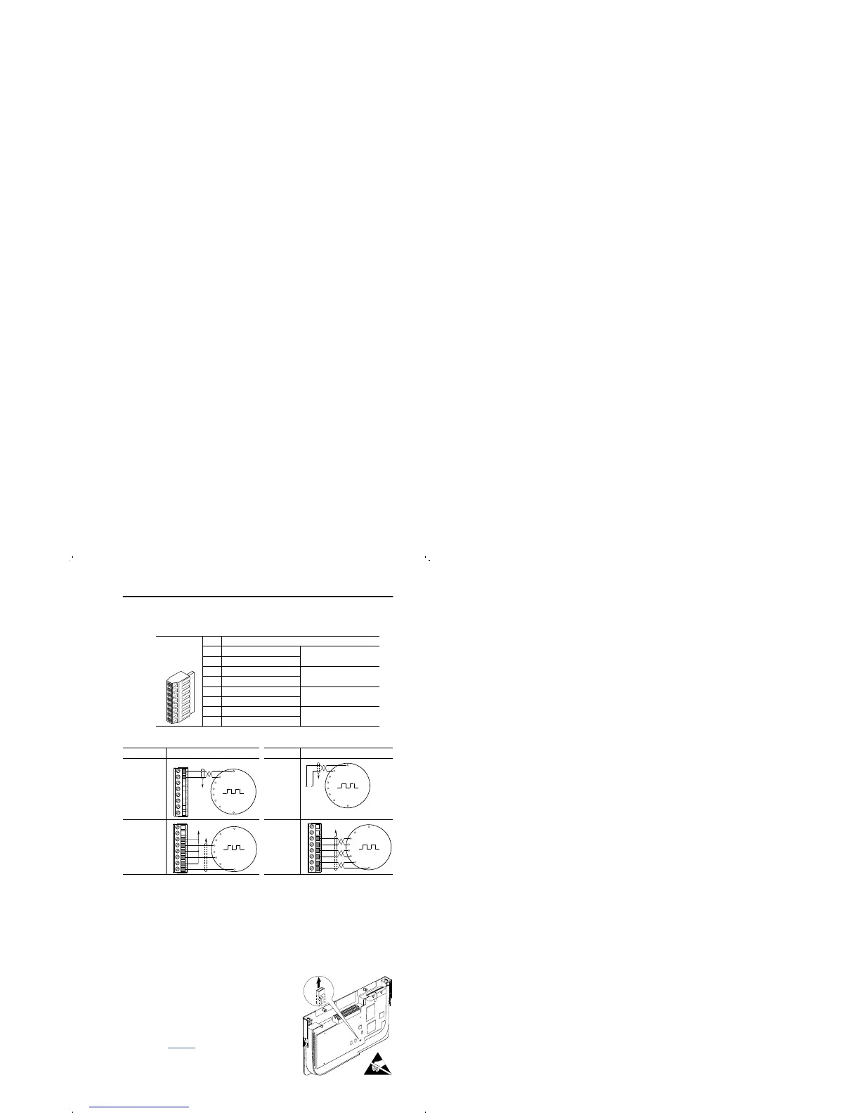
Figure 5 Encoder Terminal Designations
Figure 6 Sample Encoder Wiring
Hardware Enable Circuitry (Vector Control Option Only)
By default, the user can program a digital input as an Enable input. The
status of this input is interpreted by drive software. If the application
requires the drive to be disabled without software interpretation, a
“dedicated” hardware enable configuration can be utilized. This is done
by removing a jumper and wiring the enable input to “Digital In 6” (see
below).
1. Remove the I/O Control Cassette &
cover as described in the User Manual.
2. Locate & remove Jumper J10 on the
Main Control Board (see diagram).
3. Re-assemble cassette.
4. Wire Enable to “Digital In 6” (see
Figure 4).
5. Verify that [Digital In6 Sel], parameter
366 is set to “1, Enable.”
No. Description (refer to User Manual for encoder specifications)
See “Detail” in
User Manual
8 +12V DC Power Internal power source
250 mA.
7 +12V DC Return (Common)
6 Encoder Z (NOT) Pulse, marker or registration
input.
5 Encoder Z
4 Encoder B (NOT) Quadrature B input.
3 Encoder B
2 Encoder A (NOT) Single channel or
quadrature A input.
1 Encoder A
8
1
I/O Connection Example I/O Connection Example
Encoder
Power –
Internal Drive
Power
Internal (drive)
12V DC,
250mA
Encoder
Power –
External
Power
Source
Encoder
Signal –
Single-Ended,
Dual Channel
Encoder
Signal –
Differential,
Dual
Channel
Common
+12V DC
(200 mA)
1
2
3
4
5
6
7
8
to SHLD
+
Common
External
Power
Supply
to
SHLD
B
B NOT
A NOT
A
Z
Z NOT
to SHLD
to Power Supply
Common
1
2
3
4
5
6
7
8
to SHLD
1
2
3
4
5
6
7
8
B
Z
A NOT
B NOT
Z NOT
A
E
N
A
B
L
E
J
UM
P
E
R
J
1
0

 Loading...


