Overview P-5
Code Vol t ag e Ph. Prechg.
B240V AC3–
C400V AC3–
D480V AC3–
E600V AC
➌
3–
F690V AC3–
H540V DC
➍
–N
J650V DC
➍
–N
P540V DC
➍
–Y
R650V DC
➍
–Y
Code
Control I/O Volts
A Std. 24V DC/AC
B Std. 115V AC
CVector
➎
24V DC/AC
DVector
➎
115V AC
NStd. None
Code
Version
C ControlNet (Coax)
D DeviceNet
E EtherNet/IP
RRIO
S RS-485
NNone
Code
Operator Interface
0Blank Cover
2 Digital LCD
3 Full Numeric LCD
4 Analog LCD
5 Prog. Only LCD
Code
w/Resistor
YYes
➊
NNo
Code
CE Filter CM Choke
AYes Yes
BYes No
Code
Type
0None
1 Encoder, 12V
Code
Enclosure
AIP 20,
NEMA Type 1
NOpen
Code
w/Brake IGBT
➋
YYes
NNo
➊ Not available for Frame 3 drives or larger.
➋ Brake IGBT is standard on Frames 0-3 and optional on Frames 4-6.
➌ Note: CE Certification testing has not been performed on 600V class drives.
➍ Frames 5 & 6 Only.
➎ Vector Control Option utilizes DPI Only.
➏ Must be used with Vector Control option C or D (position 15). Positions 17-20 are only
required when custom firmware is supplied.
➐ Positions 16-20 of the catalog number are not applicable for Canada. These options
(positions 16-20) are only available as User Installed in Canada
Code Type
A User Manual
N No Manual
Code Type
20B 700
400V 60Hz Input
400V
Code
Amps kW
1P3 1.3 0.37
2P1 2.1 0.75
3P5 3.5 1.5
5P0 5.0 2.2
8P7 8.7 4.0
011 11.5 5.5
015 15.4 7.5
022 22 11
030 30 15
037 37 18.5
043 43 22
056 56 30
072 72 37
085 85 45
105 105 55
125 125 55
140 140 75
170 170 90
205 205 110
260 260 132
600V 60Hz Input
➌
600V
Code
Amps HP
1P7 1.7 1.0
2P7 2.7 2.0
3P9 3.9 3.0
6P1 6.1 5.0
9P0 9.0 7.5
011 11 10
017 17 15
022 22 20
027 27 25
032 32 30
041 41 40
052 52 50
062 62 60
077 77 75
099 99 100
125 125 125
144 144 150
208/240V 60Hz Input
208V 240V
Code
Amps Amps HP
2P2 2.5 2.2 0.5
4P2 4.8 4.2 1.0
6P8 7.8 6.8 2.0
9P6 11 9.6 3.0
015 17.5 15.3 5.0
022 25.3 22 7.5
028 32.2 28 10
042 48.3 42 15
052 56 52 20
070 78.2 70 25
080 92 80 30
104 120 104 40
130 130 130 50
154 177 154 60
192 221 192 75
690V 60Hz Input
690V
Code
Amps kW
052 52 45
060 60 55
082 82 75
098 98 90
119 119 110
142 142 132
480V 60Hz Input
480V
Code
Amps HP)
1P1 1.1 0.5
2P1 2.1 1.0
3P4 3.4 2.0
5P0 5.0 3.0
8P0 8.0 5.0
011 11 7.5
014 14 10
022 22 15
027 27 20
034 34 25
040 40 30
052 52 40
065 65 50
077 77 60
096 96 75
125 125 100
156 156 125
180 180 150
248 248 200
Code Type
AD➏ 60Hz Maximum
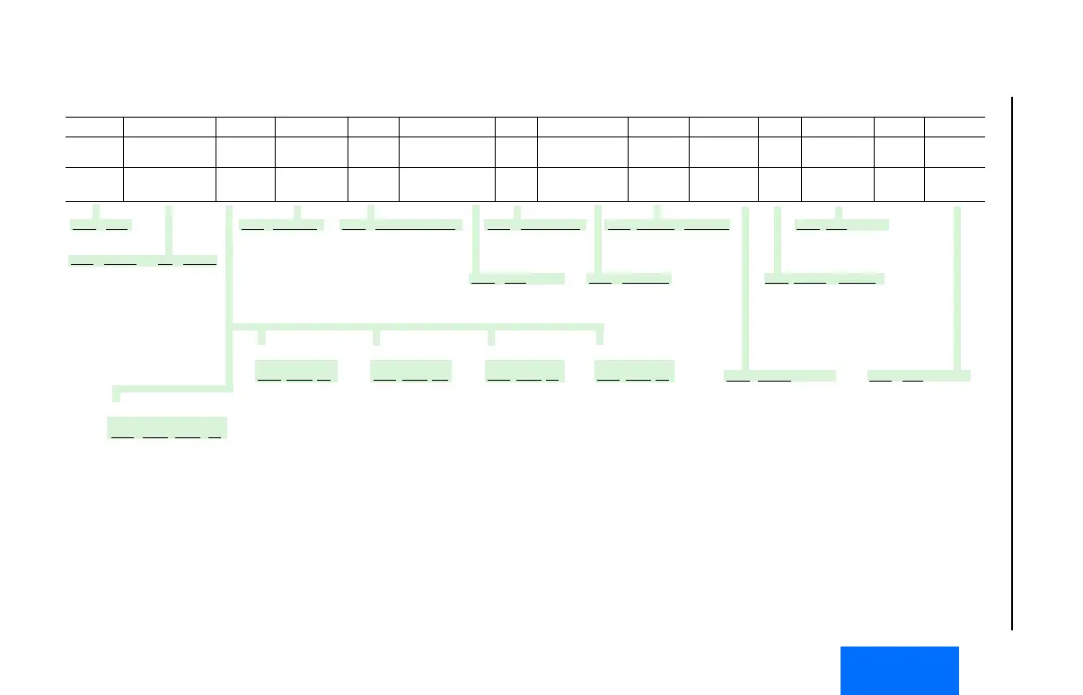
Position
1-3 4 5-7 8 9 10 11 12 13 14 15 16 ➐ 17-18➐ 19-20➐
20B D 2P1 A 3 A Y N A R C 0 NN AD
Drive Voltage Rating Rating Enclosure HIM Documentation Brake Brake Resistor Emission Comm Slot I/O Feedback Future
Use
Custom
Firmware
 Loading...


