Programming and Parameters 3-59
Applications File
INPUTS & OUTPUTS
Digital Outputs
382
386
390
[Dig Out1 OnTime]
[Dig Out2 OnTime]
[Dig Out3 OnTime]
Sets the “ON Delay” time for the digital
outputs. This is the time between the
occurrence of a condition and activation
of the relay.
Default:
Min/Max:
Units:
0.00 Secs
0.00 Secs
0.00/600.00 Secs
0.01 Secs
380
383
387
391
[Dig Out1 OffTime]
[Dig Out2 OffTime]
[Dig Out3 OffTime]
Sets the “OFF Delay” time for the digital
outputs. This is the time between the
disappearance of a condition and
de-activation of the relay.
Default:
Min/Max:
Units:
0.00 Secs
0.00 Secs
0.00/600.00 Secs
0.01 Secs
380
File
Group
No.
Parameter Name & Description
See page 3-2 for symbol descriptions
Values
Related
Vector
Vector
File
Group
No.
Parameter Name & Description
See page 3-2 for symbol descriptions
Values
Related
Applications
Torque Proving
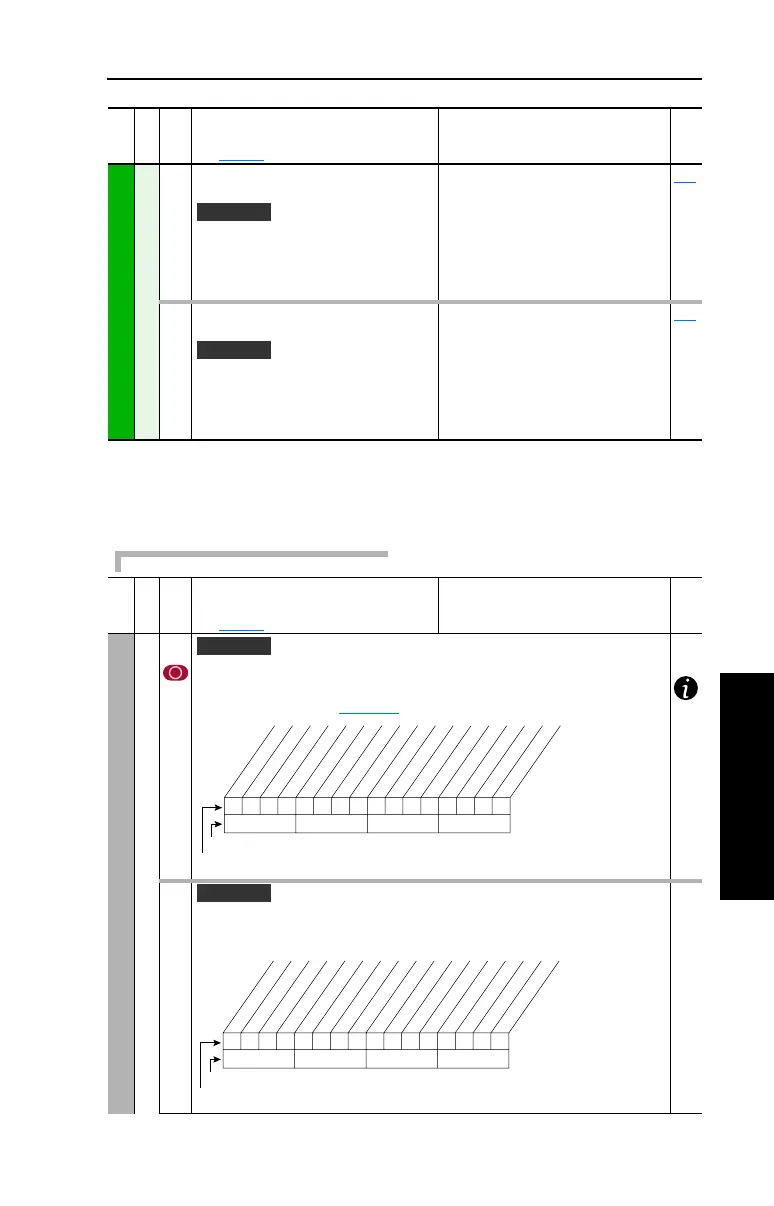
600 [TorqProve Cnfg]
Enables/disables torque/brake proving feature. When “Enabled,” [Digital Out1 Sel]
becomes the brake control. Note: this value is not changed when parameters are
reset to factory defaults (page 3-40
).
601 [TorqProve Setup]
Allows control of specific torque proving functions through a communication
device.
Vector v3
xxx 0xxxxxxxxxxxx
10 01234567891112131415
1 =Enabled
0 =Disabled
x =Reserved
Bit #
Factory Default Bit Values
Enable
Vector v3
0xx 0xxxxxxxxxxxx
10 01234567891112131415
1 =Enabled
0 =Disabled
x =Reserved
Bit #
Factory Default Bit Values
Fast Stop
Micro Pos

 Loading...


