Troubleshooting 4-13
Drive does not Start from Start or Run Inputs wired to the terminal block.
Drive does not Start from HIM.
Drive does not respond to changes in speed command.
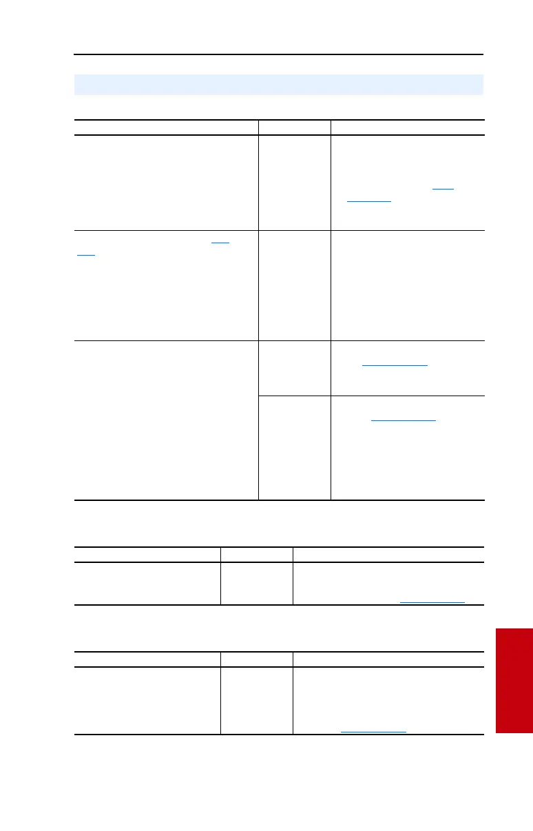
Common Symptoms and Corrective Actions
Cause(s) Indication Corrective Action
Drive is Faulted Flashing red
status light
Clear fault.
• Press Stop
• Cycle power
• Set [Fault Clear] to 1 (See
page 3-46)
• “Clear Faults” on the HIM
Diagnostic menu.
Incorrect input wiring. See pages 1-20
&
1-21
for wiring examples.
• 2 wire control requires Run, Run
Forward, Run Reverse or Jog input.
• 3 wire control requires Start and Stop
inputs.
• Jumper from terminal 25 to 26 is
required.
None Wire inputs correctly and/or install
jumper.
Incorrect digital input programming.
• Mutually exclusive choices have been
made (i.e., Jog and Jog Forward).
• 2 wire and 3 wire programming may be
conflicting.
• Exclusive functions (i.e, direction control)
may have multiple inputs configured.
• Stop is factory default and is not wired.
None Program [Digital Inx Sel] for correct
inputs. (See page 3-57)
Start or Run programming may be
missing.
Flashing yellow
status light and
“DigIn CflctB”
indication on
LCD HIM.
[Drive Status 2]
shows type 2
alarm(s).
Program [Digital Inx Sel] to resolve
conflicts. (See page 3-57)
Remove multiple selections for the
same function.
Install stop button to apply a signal at
stop terminal.
Cause(s) Indication Corrective Action
Drive is programmed for 2 wire
control. HIM Start button is
disabled for 2 wire control.
None If 2 wire control is required, no action needed.
If 3 wire control is required, program [Digital
Inx Sel] for correct inputs. (See page 3-57)
Cause(s) Indication Corrective Action
No value is coming from the source
of the command.
LCD HIM Status
Line indicates
“At Speed” and
output is 0 Hz.
1. If the source is an analog input, check
wiring and use a meter to check for
presence of signal.
2. Check [Commanded Freq] for correct
source. (See page 3-12)

 Loading...


