1-20 Installation/Wiring
I/O Wiring Examples – Standard & Vector Control Options
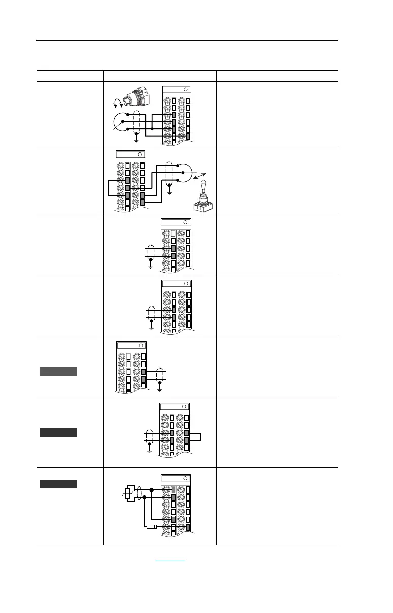
Input/Output Connection Example Required Parameter Changes
Potentiometer
Unipolar Speed
Reference
(1)
10k Ohm Pot.
Recommended
(2k Ohm Minimum)
• Adjust Scaling:
Parameters 91/92 and 325/326
• View Results:
Parameter 002
Joystick Bipolar
Speed Reference
(1)
±10V Input
• Set Direction Mode:
Parameter 190 = “1, Bipolar”
• Adjust Scaling:
Parameters 91/92 and 325/326
• View Results:
Parameter 002
Analog Input
Bipolar Speed
Reference
±10V Input
• Set Direction Mode:
Parameter 190 = “1, Bipolar”
• Adjust Scaling:
Parameters 91/92 and 325/326
• View Results:
Parameter 002
Analog Voltage
Input Unipolar
Speed Reference
0 to +10V Input
• Configure Input with parameter 320
• Adjust Scaling:
Parameters 91/92 and 325/326
• View results:
Parameter 002
Analog Current
Input Unipolar
Speed Reference
4-20 mA Input
• Configure Input for Current:
Parameter 320, Bit 1 = “1, Current”
• Adjust Scaling:
Parameters 91/92 and 325/326
• View Results:
Parameter 002
Analog Current
Input Unipolar
Speed Reference
4-20 mA Input
• Configure Input for Current:
Parameter 320 and add jumper at
appropriate terminals
• Adjust Scaling:
Parameters 91/92 and 325/326
• View results:
Parameter 002
Analog Input, PTC
PTC OT set > 5V
PTC OT cleared < 4V
PTC Short < 0.2V
• Set Drive Alarm 1:
Parameter 211, bit 11 = “True”
• Set Fault Config 1:
Parameter 238, bit 7 = “Enabled”
• Set Alarm Config 1:
Parameter 259, bit 11 = “Enabled”
(1)
Refer to the Attention statement on page 1-15 for important bipolar wiring information.
3
4
5
22
3
5
21
22
3
4
Common
+
3
4
Common
+
Standard
19
20
Common
+
Vector
3
4
19
20
Common
+
Vector
5
3.32k
Ohm
1.8k
PTC
Ferrite
Bead
1
2
22
 Loading...


