1-12 Installation/Wiring
Input Contactor Precautions
Output Contactor Precaution
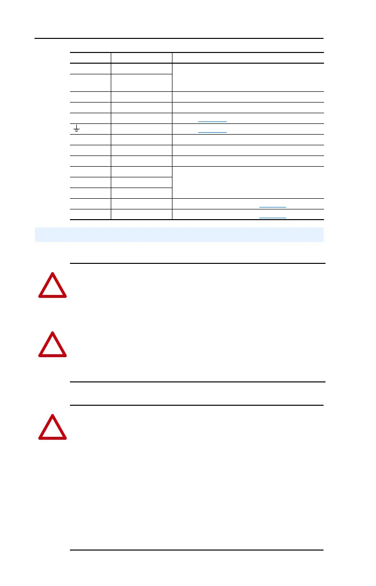
Terminal Description Notes
BR1 DC Brake (+) DB Resistor Connection - Important: Only one DB
resistor can be used with Frames 0-3. Connecting an
internal & external resistor could cause damage.
BR2 DC Brake (–)
DC+ DC Bus (+)
DC– DC Bus (–)
PE PE Ground Refer to Figure 1.3
for location on 3 Frame drives
Motor Ground Refer to Figure 1.3
for location on 3 Frame drives
U U (T1) To motor
V V (T2) To motor
W W (T3) To motor
R R (L1) AC Line Input Power
Three-Phase = R, S & T
Single-Phase = R & S Only
S S (L2)
T T (L3)
PS+ AUX (+) Auxiliary Control Voltage (see Table 1.C
)
PS– AUX (–) Auxiliary Control Voltage (see Table 1.C
)
Using Input/Output Contactors
!
ATTENTION: A contactor or other device that routinely disconnects
and reapplies the AC line to the drive to start and stop the motor can
cause drive hardware damage. The drive is designed to use control input
signals that will start and stop the motor. If an input device is used, oper-
ation must not exceed one cycle per minute or drive damage will occur.
!
ATTENTION: The drive start/stop/enable control circuitry includes
solid state components. If hazards due to accidental contact with mov-
ing machinery or unintentional flow of liquid, gas or solids exist, an
additional hardwired stop circuit may be required to remove the AC line
to the drive. An auxiliary braking method may be required.
!
ATTENTION: To guard against drive damage when using output
contactors, the following information must be read and understood.
One or more output contactors may be installed between the drive and
motor(s) for the purpose of disconnecting or isolating certain motors/
loads. If a contactor is opened while the drive is operating, power will
be removed from the respective motor, but the drive will continue to
produce voltage at the output terminals. In addition, reconnecting a
motor to an active drive (by closing the contactor) could produce
excessive current that may cause the drive to fault. If any of these
conditions are determined to be undesirable or unsafe, an auxiliary
contact on the output contactor should be wired to a drive digital input
that is programmed as “Enable.” This will cause the drive to execute a
coast-to-stop (cease output) whenever an output contactor is opened.
 Loading...


