Installation/Wiring 1-9
1. Locate the small metal tab at the bottom of the end block.
2. Press the tab in and pull the top of the block out. Repeat for next
block if desired.
3. Select appropriate transformer tap.
4. Replace block(s) in reverse order.
Power Terminal Block
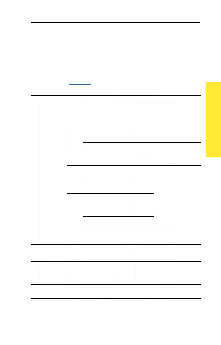
Refer to Figure 1.3 for typical locations.
Table 1.C Power Terminal Block Specifications
No. Name Frame Description
Wire Size Range
(1)
Torque
Maximum Minimum Maximum Recommended
➊
Power Terminal
Block
0 & 1 Input power and
motor connections
4.0 mm
2
(10 AWG)
0.5 mm
2
(22 AWG)
1.7 N-m
(15 lb.-in.)
0.8 N-m
(7 lb.-in.)
2 Input power and
motor connections
10.0 mm
2
(6 AWG)
0.8 mm
2
(18 AWG)
1.7 N-m
(15 lb.-in.)
1.4 N-m
(12 lb.-in.)
3 Input power and
motor connections
25.0 mm
2
(3 AWG)
2.5 mm
2
(14 AWG)
3.6 N-m
(32 lb.-in.)
1.8 N-m
(16 lb.-in.)
BR1, 2 terminals 10.0 mm
2
(6 AWG)
0.8 mm
2
(18 AWG)
1.7 N-m
(15 lb.-in.)
1.4 N-m
(12 lb.-in.)
4 Input power and
motor connections
35.0 mm
2
(1/0 AWG)
10 mm
2
(8 AWG)
4.0 N-m
(35 lb.-in.)
4.0 N-m
(35 lb.-in.)
5
(75 HP)
Input power, BR1,
2, DC+, DC– and
motor connections
50.0 mm
2
(1/0 AWG)
2.5 mm
2
(14 AWG)
See Note
(2)
PE 50.0 mm
2
(1/0 AWG)
16.0 mm
2
(6 AWG)
5
(100 HP)
Input power, DC+,
DC– and motor
70.0 mm
2
(2/0 AWG)
25.0 mm
2
(4 AWG)
BR1, 2, terminals 50.0 mm
2
(1/0 AWG)
2.5 mm
2
(14 AWG)
PE 50.0 mm
2
(1/0 AWG)
16.0 mm
2
(6 AWG)
6 Input power, DC+,
DC–, BR1, 2, PE,
motor connections
120.0 mm
2
(4/0 AWG)
2.5 mm
2
(14 AWG)
6 N-m
(52 lb.-in.)
6 N-m
(52 lb.-in.)
➋
SHLD Terminal 0-6 Terminating point
for wiring shields
— — 1.6 N-m
(14 lb.-in.)
1.6 N-m
(14 lb.-in.)
➌
AUX Terminal
Block
0-4 Auxiliary Control
Volt age
PS+, PS–
(3)
1.5 mm
2
(16 AWG)
0.2 mm
2
(24 AWG)
——
5-6 4.0 mm
2
(12 AWG)
0.5 mm
2
(22 AWG)
0.6 N-m
(5.3 lb.-in.)
0.6 N-m
(5.3 lb.-in.)
➍
Fan Terminal
Block (CB Only)
5-6 User Supplied Fan
Voltage (page 1-8
)
4.0 mm
2
(12 AWG)
0.5 mm
2
(22 AWG)
0.6 N-m
(5.3 lb.-in.)
0.6 N-m
(5.3 lb.-in.)
(1)
Maximum/minimum sizes that the terminal block will accept - these are not recommendations.
(2)
Refer to the terminal block label inside the drive.
(3)
External control power: UL Installation-300V DC, ±10%, Non UL Installation-270-600V DC, ±10%
0-3 Frame - 40 W, 165 mA, 5 Frame - 80 W, 90 mA.
 Loading...


