1-8 Installation/Wiring
AC Input Phase Selection (Frames 5 & 6 Only)
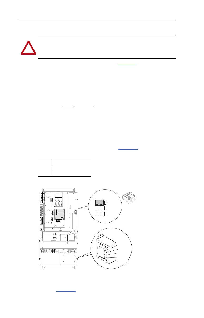
Moving the “Line Type” jumper shown in Figure 1.2 will allow single or
three-phase operation.
Important: When selecting single-phase operation, input power must
be applied to the R (L1) and S (L2) terminals only.
Selecting/Verifying Fan Voltage (Frames 5 & 6 Only)
Important: Read Attention statement above!
Frames 5 & 6 utilize a transformer to match the input line voltage to the
internal fan voltage. If your line voltage is different than the voltage class
specified on the drive nameplate, it may be necessary to change
transformer taps as shown below. Common Bus (DC input) drives
require user supplied 120 or 240V AC to power the cooling fans. The
power source is connected between “0 VAC” and the terminal
corresponding to your source voltage (see Figure 1.4
).
Table A Fan VA ratings (DC Input Only)
Figure 1.2 Typical Locations - Phase Select Jumper & Transformer (Frame 5 shown)
Frame 6 Transformer Tap Access
The transformer is located behind the Power Terminal Block in the area
shown in Figure 1.2
. Access is gained by releasing the terminal block
from the rail. To release terminal block and change tap:
!
ATTENTION: To avoid a shock hazard, ensure that all power to the
drive has been removed before performing the following.
Frame Rating (120V or 240V)
5 100 VA
6 138 VA
LINE
TYPE
SPARE 1
SPARE 2
3-PH 1-PH
480 Volt Tap
600 Volt Tap
690 Volt Tap
400 Volt Tap
Fan Voltage
Phase Selection
Jumper
WIRE RANGE: 14-1/0 AWG (2.5-35 MM
2
)
TORQUE: 32 IN-LB (3.6 N-M)
STRIP LENGTH: 0.67 IN (17 MM)
USE 75° C CU WIRE ONLY
POWER TERMINAL RATINGS
WIRE RANGE: 6-1/0 AWG (16-35 MM
2
)
TORQUE: 44 IN-LB (5 N-M)
STRIP LENGTH: 0.83 IN (21 MM)
GROUND TERMINAL RATINGS (PE)
300 VDC EXT PWR SPLY TERM (PS+, PS-)
WIRE RANGE: 22-10 AWG (0.5-4 MM
2
)
TORQUE: 5.3 IN-LB (0.6 N-M)
STRIP LENGTH: 0.35 IN (9 MM)
17
21
INPUT ACOUTPUT
Optional
Communications
Module
9
 Loading...


