Installation/Wiring 1-11
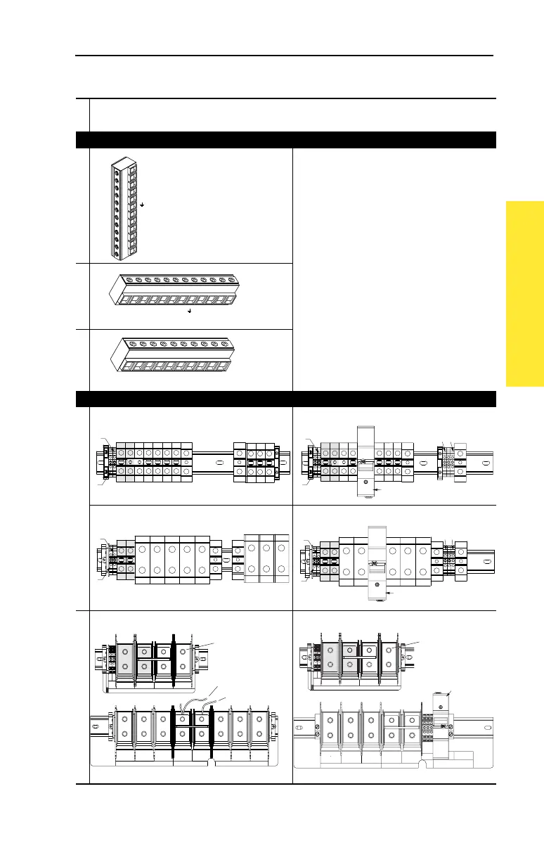
Figure 1.4 Power Terminal Block
Frame
Terminal Block
0
+
1
* Note:
Shaded BR1 & BR2 Terminals will only be
present on drives ordered with the Brake Option.
2
3
+
4
480V AC Input 650V DC Input
5 75 HP, Normal Duty 75 HP, Normal Duty
100 HP, Normal Duty 100 HP, Normal Duty
6 125-200 HP, Normal Duty 125-200 HP, Normal Duty
BR1
BR2
DC+
DC–
PE
U (T1)
V (T2)
W (T3)
R (L1)
S (L2)
T (L3)
T
(L3)
S
(L2)
R
(L1)
W
(T3)
V
(T2)
U
(T1)
PEDC–DC+BR2BR1
T
(L3)
S
(L2)
R
(L1)
W
(T3)
V
(T2)
U
(T1)
DC–DC+BR2BR1
T/L3S/L2R/L1PEPEW/T3V/T2U/T1DC–DC+
BR1*/
DC+
BR2*
PS–
PS+
240
VAC
120
VAC
0
VAC
PE PEW/T3V/T2
Precharge Resistor Fuse – FWP-15A14F
(Common Bus Drives w/Precharge Only)
U/T1DC–DC+
BR1*/
DC+
BR2*
PS–
PS+
T/L3S/L2R/L1
PEPE
W/T3V/T2U/T1DC–DC+
BR1*/
DC+
BR2*
PS–
PS+
240
VAC
120
VAC
0
VAC
PEPE
W/T3V/T2U/T1DC–DC+
BR1*/
DC+
BR2*
PS–
PS+
Precharge Resistor Fuse – FWP-15A14F
(Common Bus Drives w/Precharge Only)
USE 75 C
COPPER WIRE
ONLY
TORQUE
52 IN-LB
(6 N-M)
U
T1
DC–DC+BR1BR2
V
T2
W
T3
R
L1
S
L2
INPUTOUTPUT
T
L3
PE PE
USE 75 C COPPER WIRE ONLY, TORQUE 52 IN-LB (6 N-M)
22-10
AWG
5.3 IN-LB
(0.6 N-M)
WIRE STRIP
PS+
PS–
Common Mode Capacitor
& MOV Jumpers
Input Filter Capacitor
M8 Stud (All Terminals)
Max. Lug Width = 25.4 mm (1 in.)
DC–DC+BR1BR2
USE 75 C COPPER WIRE ONLY, TORQUE 52 IN-LB (6 N-M)
22-10
AWG
5.3 IN-LB
(0.6 N-M)
WIRE STRIP
PS+
PS–
U
T1
V
T2
W
T3
PE PE
USE 75 C
COPPER WIRE
ONLY
TORQUE
52 IN-LB
(6 N-M)
OUTPUT
22-10 AWG
5.3 IN-LB
(0.6 N-M)
FAN
INPUT
1-PHASE
0 VAC
120 VAC
240 VAC
Precharge Resistor
Fuse
FWP-15A14F
(Common Bus Drives
w/Precharge Only)
M8 Stud (All Terminals)
Max. Lug Width = 25.4 mm (1 in.)
 Loading...


