Installation/Wiring 1-13
Bypass Contactor Precaution
PowerFlex 700 drives contain protective MOVs and common mode
capacitors that are referenced to ground. To guard against drive damage,
these devices should be disconnected if the drive is installed on an
ungrounded distribution system where the line-to-ground voltages on
any phase could exceed 125% of the nominal line-to-line voltage. To
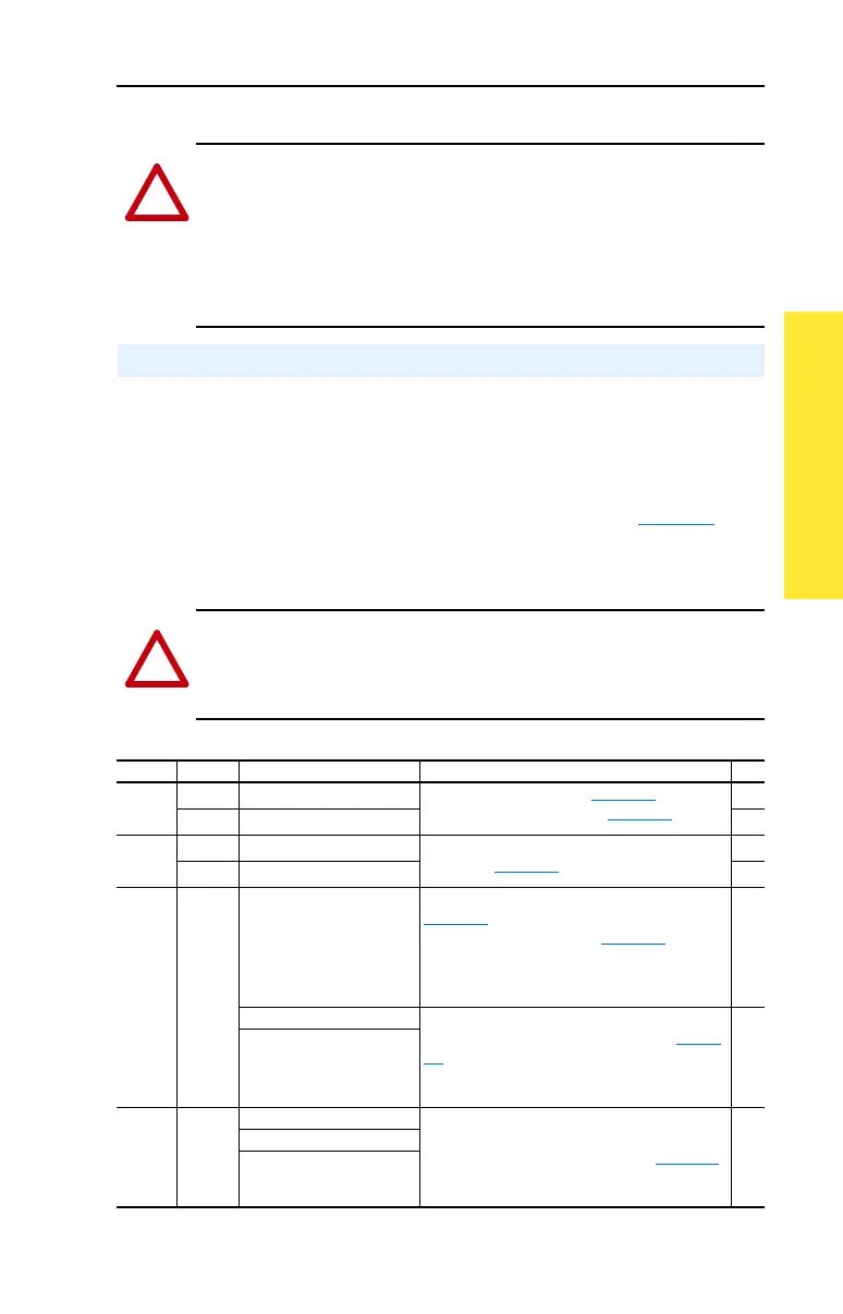
disconnect these devices, remove the jumper(s) listed in Table 1.D
.
Jumpers can be removed by carefully pulling the jumper straight out. See
Wiring and Grounding Guidelines for PWM AC Drives, publication
DRIVES-IN001 for more information on ungrounded systems.
Table 1.D Jumper Removal
(1)
(1)
Important: Do Not remove jumpers if the distribution system is grounded.
!
ATTENTION: An incorrectly applied or installed bypass system can
result in component damage or reduction in product life. The most
common causes are:
• Wiring AC line to drive output or control terminals.
• Improper bypass or output circuits not approved by Allen-Bradley.
• Output circuits which do not connect directly to the motor.
Contact Allen-Bradley for assistance with application or wiring.
Disconnecting MOVs and Common Mode Capacitors
!
ATTENTION: To avoid an electric shock hazard, verify that the
voltage on the bus capacitors has discharged before removing/installing
jumpers. Measure the DC bus voltage at the +DC & –DC terminals of
the Power Terminal Block. The voltage must be zero.
Frames Jumper Component Jumper Location No.
0, 1 PEA Common Mode Capacitors Remove the I/O Cassette (page 1-16
). Jumpers
located on the Power Board (Figure 1.5
).
➊
PEB MOV’s
➋
2-4 PEA Common Mode Capacitors Jumpers are located above the Power Terminal
Block (see Figure 1.5
).
➌
PEB MOV’s
➍
5 Wire Common Mode Capacitors Remove the I/O Cassette as described on
page 1-16
. The green/yellow jumper is located
on the back of chassis (see Figure 1.5
for loca-
tion). Disconnect, insulate and secure the wire
to guard against unintentional contact with
chassis or components.
➎
MOV’s Note location of the two green/yellow jumper
wires next to the Power Terminal Block (Figure
1.5). Disconnect, insulate and secure the wires
to guard against unintentional contact with
chassis or components.
➏
Input Filter Capacitors
6 Wire Common Mode Capacitors Remove the wire guard from the Power Terminal
Block. Disconnect the three green/yellow wires
from the two “PE” terminals shown in Figure 1.4
.
Insulate/secure the wires to guard against unin-
tentional contact with chassis or components.
MOV’s
Input Filter Capacitors

 Loading...


