1-16 Installation/Wiring
Table 1.F Recommended Control Wire for Digital I/O
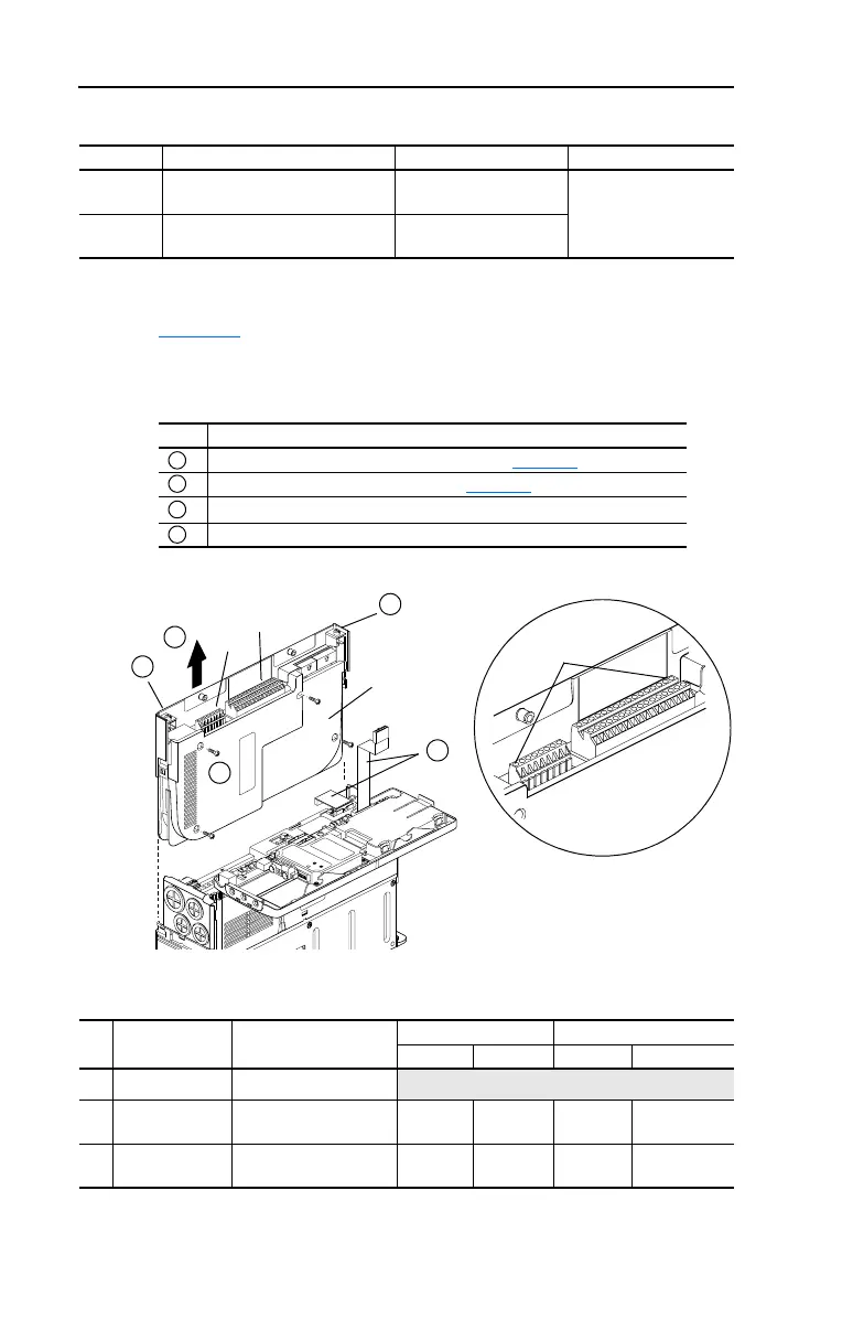
The I/O Control Cassette
Figure 1.6 shows the I/O Control Cassette and terminal block locations.
The cassette provides a mounting point for the various PowerFlex 700
I/O options. To remove the cassette, follow the steps below. Cassette
removal will be similar for all frames (0 Frame drive shown).
Figure 1.6 PowerFlex 700 Typical Cassette & I/O Terminal Blocks
I/O Terminal Blocks
Table 1.G I/O Terminal Block Specifications
Type Wire Type(s) Description Min. Insulation Rating
Unshielded Per US NEC or applicable national
or local code
– 300V,
60° C (140° F)
Shielded Multi-conductor shielded cable
such as Belden 8770(or equiv.)
0.750 mm
2
(18AWG), 3
conductor, shielded.
Step Description
Disconnect the two cable connectors shown in Figure 1.6
.
Loosen the two screw latches shown in Figure 1.6
.
Slide the cassette out.
Remove screws securing cassette cover to gain access to the boards.
A
B
C
D
BR1
B
R
2
D
C
+
DC-
P
E
U/T1
V/T2
W/T3
R/L1
L2
➌
➋
➊
B
A
C
B
D
Pin 1
Detail
No. Name Description
Wire Size Range
(2)
Torque
Maximum Minimum Maximum Recommended
➊
I/O Cassette Removable I/O Cassette
➋
I/O Terminal
Block
Signal & control
connections
2.1 mm
2
(14 AWG)
0.30 mm
2
(22 AWG)
0.6 N-m
(5.2 lb.-in.)
0.6 N-m
(5.2 lb.-in.)
➌
Encoder
Ter mi n a l B lo ck
(1)
Encoder power & signal
connections
0.75 mm
2
(18 AWG)
0.196 mm
2
(24 AWG)
0.6 N-m
(5.2 lb.-in.)
0.6 N-m
(5.2 lb.-in.)
(1)
Not available with Standard Control option.
(2)
Maximum/minimum that the terminal block will accept - these are not recommendations.
 Loading...


