1-14 Installation/Wiring
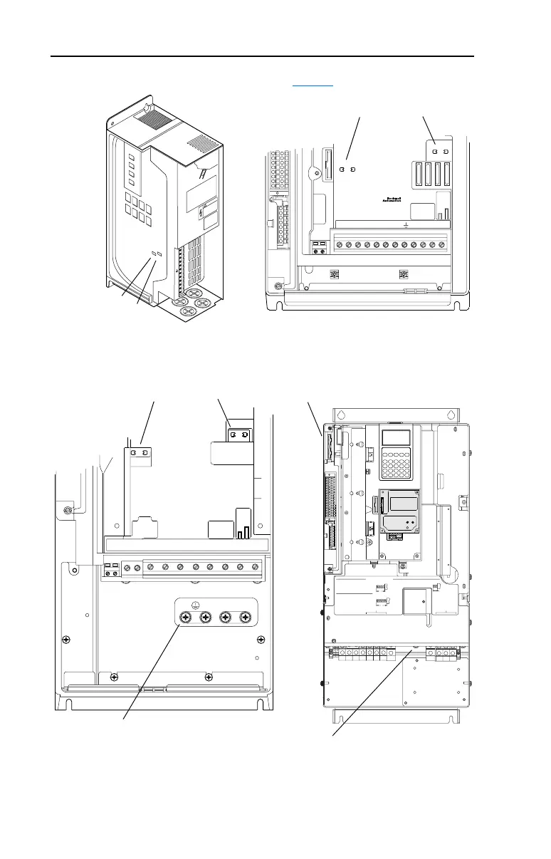
Figure 1.5 Typical Jumper Locations (see Table 1.D for description)
BR1 BR2 DC+ DC- U/T1 V/T2 W/T3
SHLD SHLD
PE R/L1 S/L2 T/L3
PE 2
MOV-PE JMPR
PE 1
AUX IN+ AUX OUT–
75C Cu Wire
6 AWG [10MM
2
] Max.
12 IN. LBS.
1.4 N-M
} TORQUE
WIRE
STRIP
CONTROL
POWER
PE 4
PE 3
DC FILTER CAP-PE JMPR
BR1
BR2
DC+
DC–
PE
U/T1
V/T2
W/T3
R/L1
S/L2
T/L3
Use 75C Wire Only
#10-#14 AWG
Torque to 7 in-lbs
!
DANGER
BR1 BR2 DC+ DC- U/T1 V/T2 W/T3 R/L1 S/L2 T/L3
PE B
PE A
75C Cu Wire
3 AWG [25MM
2
] Max.
16 IN. LBS.
1.8 N-M
} TORQUE
WIRE
STRIP
CONTROL
POWER
AUX IN
+ –
SHLD
SHLD
PE
75C Cu Wire
6 AWG [10MM
2
] Max.
BR1 BR2
12 IN. LBS.
1.4 N-M
} TORQUE
Frames 0 & 1
(I/O Cassette Removed)
Frame 2
➋
➌
➍
➊
➏
➎
WIRE RANGE: 14-1/0 AWG (2.5-35 MM
2
)
TORQUE: 32 IN-LB (3.6 N-M)
STRIP LENGTH: 0.67 IN (17 MM)
USE 75° C CU WIRE ONLY
POWER TERMINAL RATINGS
WIRE RANGE: 6-1/0 AWG (16-35 MM
2
)
TORQUE: 44 IN-LB (5 N-M)
STRIP LENGTH: 0.83 IN (21 MM)
GROUND TERMINAL RATINGS (PE)
300 VDC EXT PWR SPLY TERM (PS+, PS-)
WIRE RANGE: 22-10 AWG (0.5-4 MM
2
)
TORQUE: 5.3 IN-LB (0.6 N-M)
STRIP LENGTH: 0.35 IN (9 MM)
17
21
INPUT ACOUTPUT
Optional
Communications
Module
9
Frame 5
➌
➍
Frames 3 & 4
Important: Do Not discard or replace grounding hardware.

 Loading...


