4-12 Troubleshooting
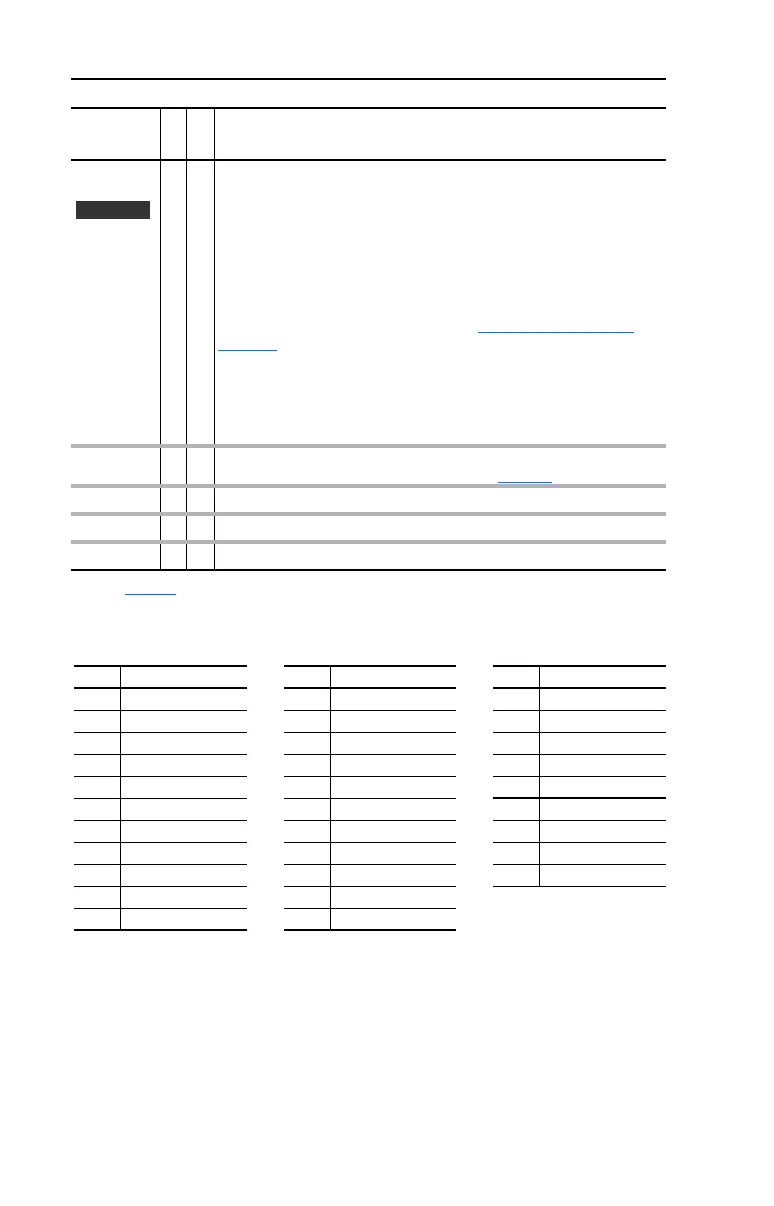
Table 4.D Alarm Cross Reference
TB Man Ref
Cflct
30
➁
Occurs when:
• “Auto/Manual” is selected (default) for [Digital In3 Sel], parameter 363
and
• [TB Man Ref Sel], parameter 96 has been reprogrammed.
No other use for the selected analog input may be programmed.
Example: If [TB Man Ref Sel] is reprogrammed to “Analog In 2,” all of the
factory default uses for “Analog In 2” must be reprogramed (such as
parameters 90, 117, 128 and 179). See also Auto/Manual Examples
on
page 1-23.
To correct:
• Verify/reprogram the parameters that reference an analog input
or
• Reprogram [Digital In3] to another function or “Unused.”
Tor qP rove
Cflct
49
➁
When [TorqProve Cnfg] is enabled, [Motor Cntl Sel], [Feedback Select] and
[Motor Fdbk Type] must be properly set (refer to page C-4
).
UnderVoltage 2
➀
The bus voltage has dropped below a predetermined value.
VHz Neg Slope
24
➁
[Torq Perf Mode] = “Custom V/Hz” & the V/Hz slope is negative.
Waking 11
➀
The Wake timer is counting toward a value that will start the drive.
(1)
See page 4-1 for a description of alarm types.
Alarm
No.
Type
(1)
Description
Vector
No.
(1)
Alarm No.
(1)
Alarm No.
(1)
Alarm
1 Precharge Active 13 In Phase Loss 25 IR Volts Range
2 UnderVoltage 14 Load Loss 26 FluxAmpsRef Rang
3 Power Loss 15 Ground Warn 27 Speed Ref Cflct
4 Start At PowerUp 17 Dig In ConflictA 28 Ixo Vlt Rang
5 Analog in Loss 18 Dig In ConflictB 29 Sleep Config
6 IntDBRes OvrHeat 19 Dig In ConflictC 30 TB Man Ref Cflct
8 Drive OL Level 1 20 Bipolar Conflict 31 PTC Conflict
9 Drive OL Level 2 21 Motor Type Cflct 32 Brake Slipped
10 Decel Inhibt 22 NP Hz Conflict 49 Torq Prove Cflct
11 Waking 23 MaxFreq Conflict
12 Motor Thermistor 24 VHz Neg Slope
(1)
Alarm numbers not listed are reserved for future use.
 Loading...


