3-2 Programming and Parameters
File
Group
No.
Parameter Name & Description Values
Related
UTILITY
Drive . . .
198 [Load Frm Usr Set]
Loads a previously saved set of
parameter values from a selected user
set location in drive nonvolatile memory
to active drive memory.
Default:
Options:
0
0
1
2
3
“Ready”
“Ready”
“User Set 1”
“User Set 2”
“User Set 3”
199
Diagnostics
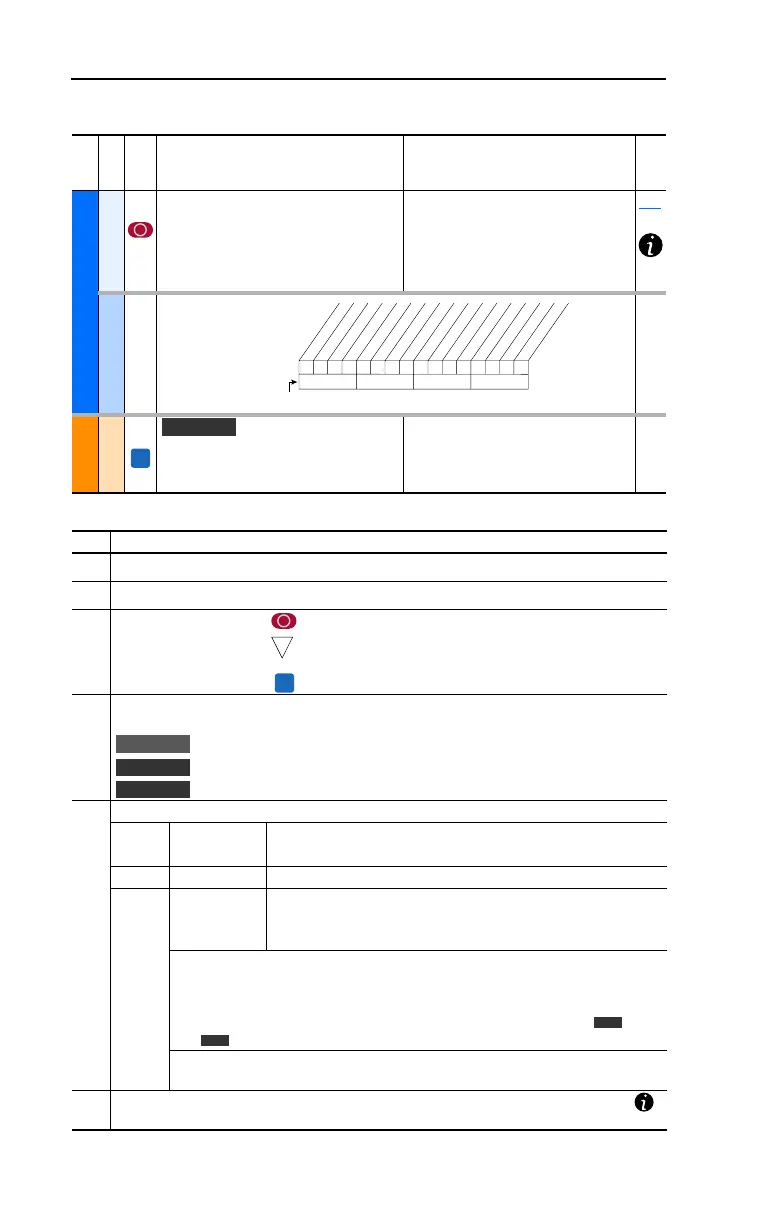
216 [Dig In Status]
Status of the digital
inputs.
MOTOR . . .
Torq . . .
434 [Torque Ref B Mult]
Defines the value of the multiplier for the
[Torque Ref B Sel] selection.
Default:
Min/Max:
Units:
1.0
–/+32767.0
0.1
000000xxxxxxxxxx
10 01234567891112131415
1 = Input Present
0 = Input Not Present
x = Reserved
Bit #
Digital In1
Digital In2
Digital In3
Digital In4
Digital In5
Digital In6
FV
Vector
➊➌➋➏➎➍
No. Description
➊
File – Lists the major parameter file category.
➋
Group – Lists the parameter group within a file.
➌
No. – Parameter number. = Parameter value can not be changed until drive is stopped.
= 32 bit parameter in the Standard Control option. All
parameters in the Vector Control option are 32 bit.
= Parameter only displayed when [Motor Cntl Sel] is set to “4.”
➍
Parameter Name & Description – Parameter name as it appears on an LCD HIM, with a brief
description of the parameters function.
= This parameter is specific to the Standard Control Option.
= This parameter will only be available with the Vector Control option.
= Only available with Vector Control option firmware version 3.xxx & later.
➎
Values – Defines the various operating characteristics of the parameter. Three types exist.
ENUM Default:
Options:
Lists the value assigned at the factory. “Read Only” = no default.
Displays the programming selections available.
Bit Bit: Lists the bit place holder and definition for each bit.
Numeric Default:
Min/Max:
Units:
Lists the value assigned at the factory. “Read Only” = no default.
The range (lowest and highest setting) possible for the parameter.
Unit of measure and resolution as shown on the LCD HIM.
Important: Some parameters will have two unit values:
• Analog inputs can be set for current or voltage with [Anlg In Config], param. 320.
• Setting [Speed Units], parameter 79 on Vector Control drives selects Hz or RPM.
• Values that pertain to Vector Control drives only will be indicated by “ ” or
“ ” for Vector firmware 3.xxx and later.
Important: When sending values through DPI ports, simply remove the decimal
point to arrive at the correct value (i.e. to send “5.00 Hz,” use “500”).
➏
Related – Lists parameters (if any) that interact with the selected parameter. The symbol “ ”
indicates that additional parameter information is available in Appendix C.
32
FV
Standard
Vector
Vector v3
Vector
v3
 Loading...


