Programming and Parameters 3-19
MOTOR CONTROL
Torq Attributes
435 [Torque Setpoint]
[Torque Setpoint1]
Provides an internal fixed value for
Torque Setpoint when [Torque Ref Sel] is
set to “Torque Setpt.”
Default:
Min/Max:
Units:
0.0%
–/+800.0%
0.1%
053
436 [Pos Torque Limit]
Defines the torque limit for the positive
torque reference value. The reference will
not be allowed to exceed this value.
Default:
Min/Max:
Units:
200.0%
0.0/800.0%
0.1%
053
437 [Neg Torque Limit]
Defines the torque limit for the negative
torque reference value. The reference will
not be allowed to exceed this value.
Default:
Min/Max:
Units:
–200.0%
–800.0/0.0%
0.1%
053
438 [Torque Setpoint2]
Provides an internal fixed value for
Torque Setpoint when [Torque Ref Sel] is
set to “Torque Setpt 2.”
Default:
Min/Max:
Units:
0.0%
–/+800.0%
0.1%
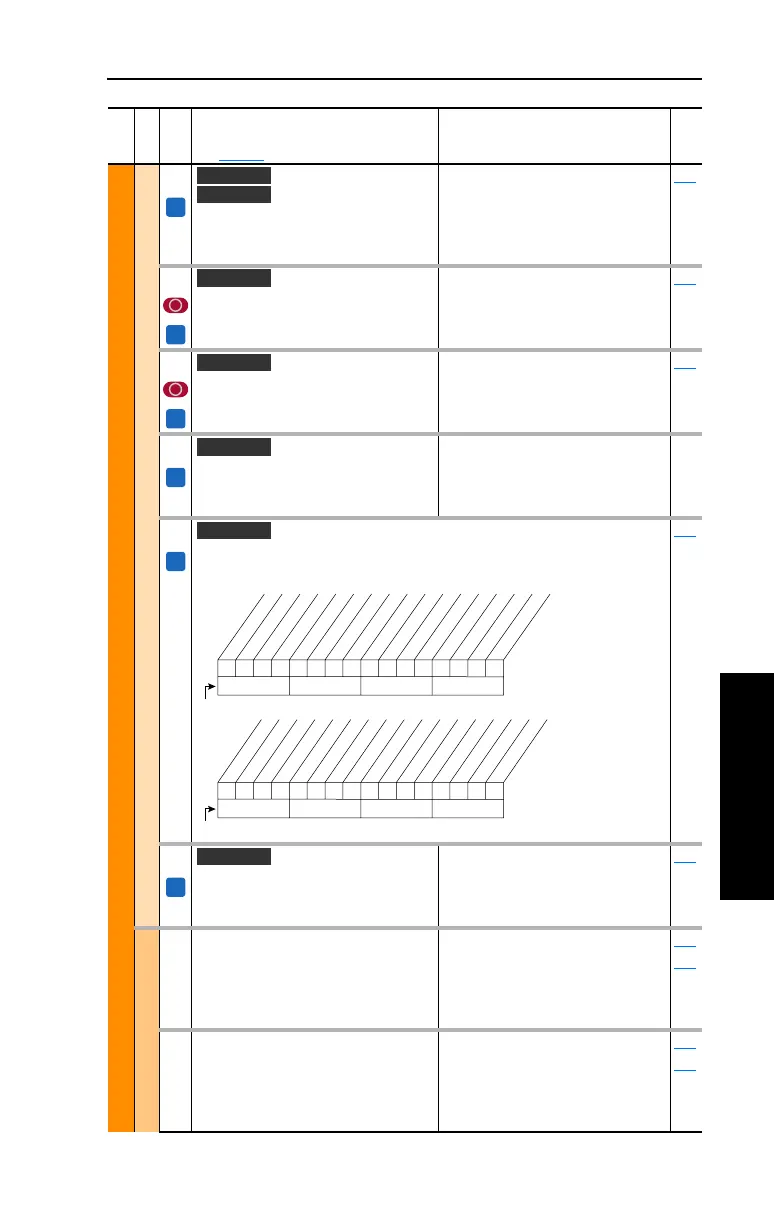
440 [Control Status]
Displays a summary status of any condition that may
be limiting either the current or the torque reference.
Read Only 053
441 [Mtr Tor Cur Ref]
Displays the torque current reference
value that is present at the output of the
current rate limiter (parameter 154).
Default:
Min/Max:
Units:
Read Only
–/+32767.0 Amps
0.01 Amps
053
Volts per Hertz
069 [Start/Acc Boost]
Sets the voltage boost level for starting
and acceleration when “Custom V/Hz”
mode is selected. Refer to parameter 083
[Overspeed Limit].
Default:
Min/Max:
Units:
Based on Drive Rating
0.0/[Motor NP Volts] x 0.25
0.1 VAC
053
070
070 [Run Boost]
Sets the boost level for steady state or
deceleration when “Fan/Pmp V/Hz” or
“Custom V/Hz” modes are selected. See
parameter 083 [Overspeed Limit].
Default:
Min/Max:
Units:
Based on Drive Rating
0.0/[Motor NP Volts] x 0.25
0.1 VAC
053
069
File
Group
No.
Parameter Name & Description
See page 3-2 for symbol descriptions
Values
Related
FV
Vector
Vector v3
FV
Vector
FV
Vector
FV
Vector v3
FV
Vector
0000000000000000
10 01234567891112131415
1 =Condition True
0 =Condition False
x =Reserved
Bit #
NegTrqCurLim
PosTrqCurLim
NegFlxCurLim
PosFlxCurLim
NegTrqLimit
PosTrqLimit
NegPwrTrqLim
PosPwrTrqLim
Min Slip Lim
Max Slip Lim
MinTrqCurLim
VelTrqRef
TorqRef
FldWeakSts
Observe Sts
VltLimLeakag
00000xxxxxxxxxxx
26 161718192021222324252728293031
1 =Condition True
0 =Condition False
x =Reserved
Bit #
VltLimStator
DrvVoltLim
FluxBrake
Economize
RevPhaseMot
FV
Vector

 Loading...


