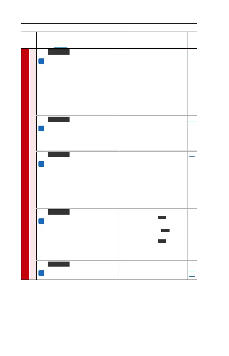
3-30 Programming and Parameters
SPEED COMMAND
Speed Regulator
446 [Kp Speed Loop]
Controls the proportional error gain of the
speed regulator. The drive automatically
adjusts [Kp Speed Loop] when a
non-zero value is entered for [Speed
Desired BW] or an auto-tune is
performed. Typically, manual adjustment
of this parameter is needed only if
system inertia cannot be determined
through an autotune. [Speed Desired
BW] is set to “0” when a manual
adjustment is made to this parameter.
Default:
Min/Max:
Units:
6.3
0.0/200.0
0.1
053
447 [Kf Speed Loop]
Controls the feed forward gain of the
speed regulator. Setting the Kf gain
greater than zero reduces speed
feedback overshoot in response to a step
change in speed reference.
Default:
Min/Max:
Units:
0.0
0.0/0.5
0.1
053
449 [Speed Desired BW]
Sets the speed loop bandwidth and
determines the dynamic behavior of the
speed loop. As bandwidth increases, the
speed loop becomes more responsive
and can track a faster changing speed
reference.
Adjusting this parameter will cause the
drive to calculate and change [Ki Speed
Loop] and [Kp Speed Loop] gains.
Default:
Min/Max:
Units:
0.0 Radians/Sec
0.0/250.0 Radians/Sec
0.1 Radians/Sec
053
450 [Total Inertia]
Represents the time in seconds, for a
motor coupled to a load to accelerate
from zero to base speed, at rated motor
torque. The drive calculates Total Inertia
during the autotune inertia procedure.
Adjusting this parameter will cause the
drive to calculate and change [Ki Speed
Loop] and [Kp Speed Loop] gains.
Default:
Min/Max:
Units:
1.25 Secs
0.10 Secs
0.1/600.0 Secs
0.01/600.00
0.1 Secs
0.01 Secs
053
451 [Speed Loop Meter]
Value of the speed regulator output.
Default:
Min/Max:
Units:
Read Only
–/+800.0%/Hz/RPM
0.1%/Hz/RPM
053
121
079
File
Group
No.
Parameter Name & Description
See page 3-2 for symbol descriptions
Values
Related
FV
Vector
FV
Vector
FV
Vector
FV
Vector
v3
v3
v3
FV
Vector v3

 Loading...


